High-pressure fuel pump drive circuit for engine

a high-pressure fuel pump and drive circuit technology, applied in the direction of positive-displacement liquid engines, magnetic bodies, electric control, etc., can solve the problems of unintentional behavior of fuel pressure and inability to stabilize fuel pressure, so as to reduce the generation of heat in the device, accelerate the fall time, and save energy consumption

Active Publication Date: 2011-02-01
HITACHI ASTEMO LTD
View PDF7 Cites 5 Cited by
  • Summary
  • Abstract
  • Description
  • Claims
  • Application Information

AI Technical Summary

Benefits of technology

[0015]Additionally, the present invention also provides a high-pressure fuel pump drive circuit which can be obtained by modifying the structure of the aforementioned high-pressure fuel pump drive circuit in such a manner that the Zener diode is omitted and that the switching element disposed parallel with the Zener diode is replaced by a clamp Zener diode-attached IPD, thus obtaining almost the same effects as obtainable in the aforementioned high-pressure fuel pump drive circuit.
[0017]According to the present invention, it is possible to secure a steady state subsequent to the build-up of electric current inflow and to perform, during the entire period of this steady state, current feedback by means of flywheel diode which makes it possible to save the consumption of energy. On the occasion of falling the electric current, a Zener diode is employed for enabling the energy to be instantaneously consumed, thereby accelerating the fall time of electric current flowing into the solenoid coil of the high-pressure pump, thus suppressing the generation of heat in the device.

Problems solved by technology

As long as this condition is kept unchanged, the controllability of high-pressure fuel pump would be deteriorated and hence the fuel pressure cannot be stabilized.
Further, when the rotational speed of engine is increased, there are many possibilities that unintentional behavior of fuel pressure may be caused to occur.

Method used


Image

  • High-pressure fuel pump drive circuit for engine
  • High-pressure fuel pump drive circuit for engine
  • High-pressure fuel pump drive circuit for engine

Examples


example 1

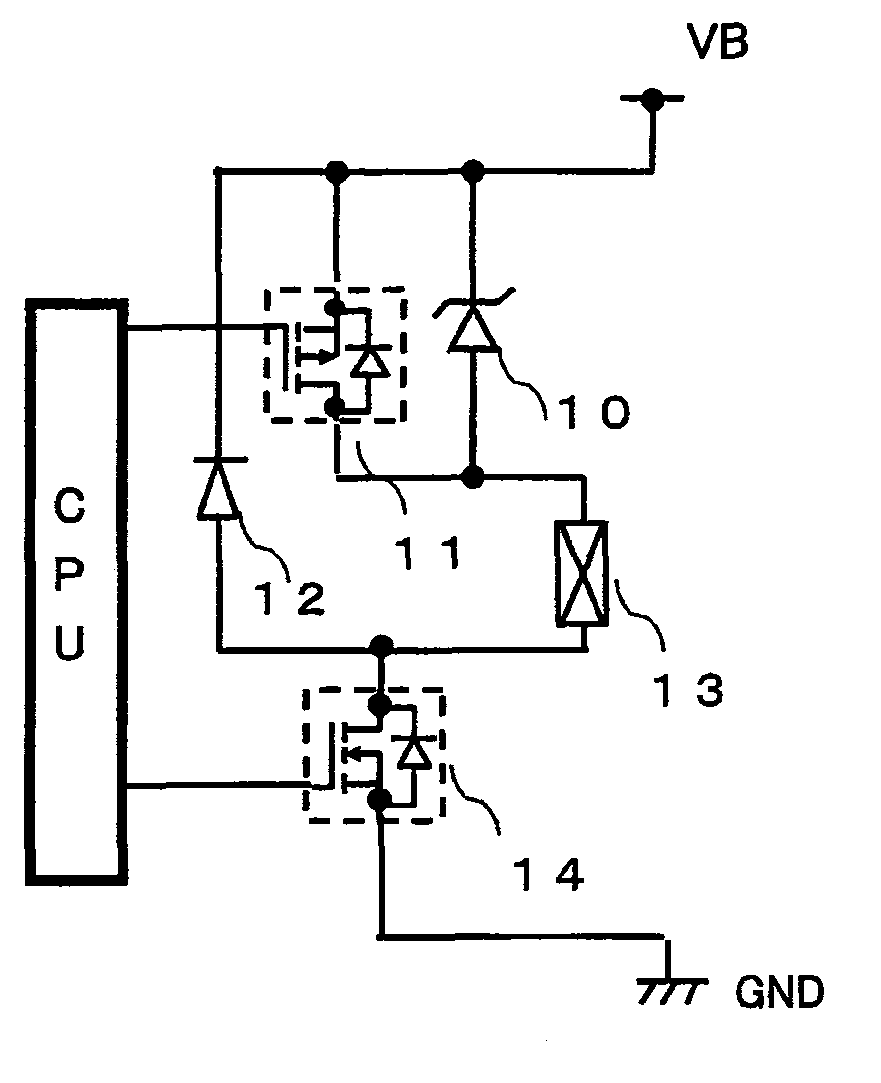
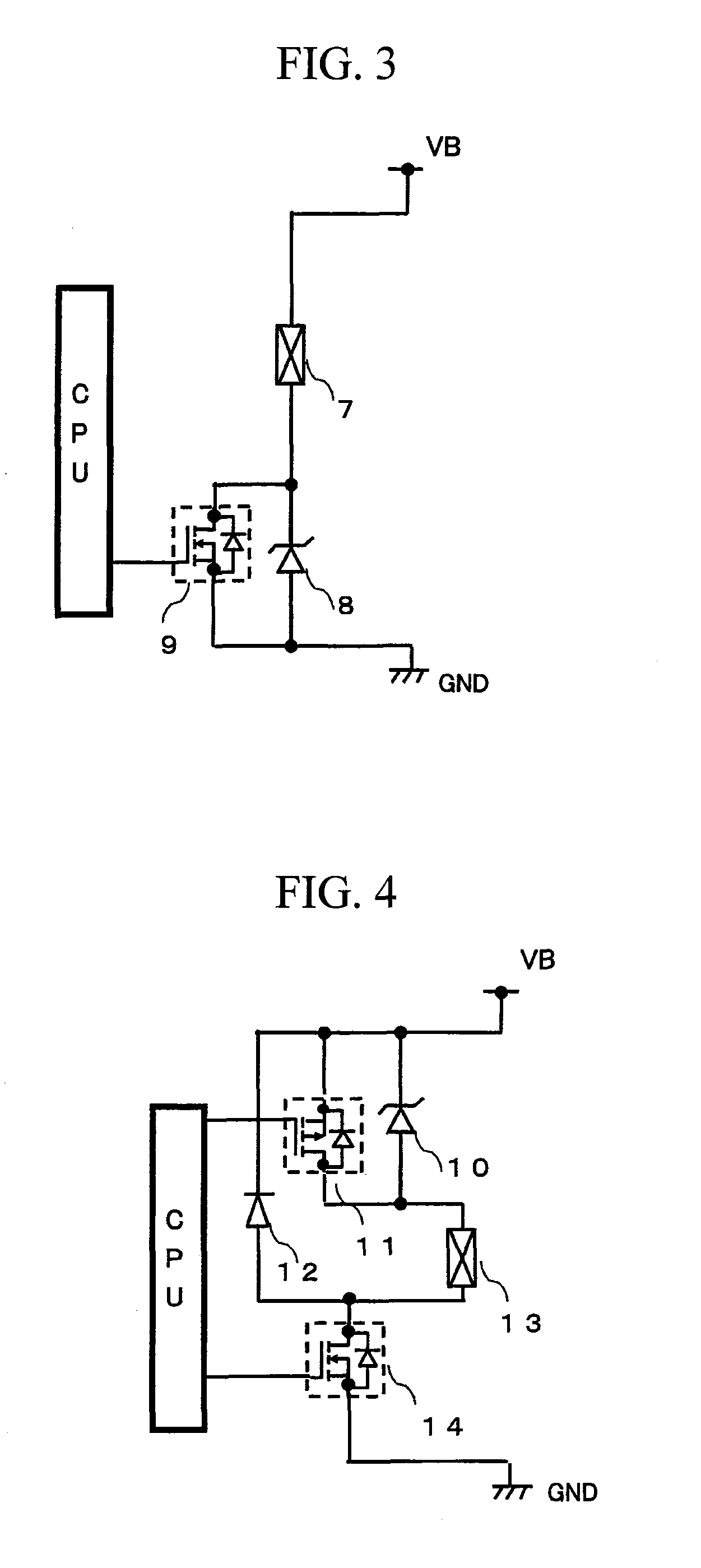
[0031]FIG. 4 illustrates a circuit configuration of a high-pressure fuel pump drive circuit for engine according to Example 1.

[0032]In this circuit, the solenoid 13 of high-pressure pump is connected with the drain of switching MOSFET (Nch) 14, and the cathode of flywheel diode 12 is connected with the source voltage VB and the anode of flywheel diode 12 is connected with the solenoid. Further, the cathode of Zener diode 10 is connected with the VB and the anode thereof is connected with the solenoid coil. The MOSFET (Pch) 11 is connected, in parallel, with the Zener diode. When an input voltage is impressed to the gates of the MOSFET (Pch) 11 and the MOSFET (Nch) 14, not only the MOSFET (Pch) 11 but also the MOSFET (Nch) 14 is turned ON, permitting an electric current IL to flow into the solenoid coil 13. At this moment, the drain voltage VD of MOSFET (Nch) 14 is caused to fall from the VB to about zero volt and, at the same time, the electric current IL flowing through the solenoi...

example 2

[0037]FIG. 6 illustrates a circuit configuration of a high-pressure fuel pump drive circuit for engine according to Example 2.

[0038]In this circuit, the solenoid coil 20 of high-pressure pump is connected with the drain of switching MOSFET (Pch) 19, and the cathode of flywheel diode 21 is connected with the drain of switching MOSFET (Pch) 19 and the anode of flywheel diode 21 is connected with the GND. Further, the cathode of Zener diode 22 is connected with the solenoid coil 20 and the anode thereof is connected with the GND. The MOSFET (Nch) 23 is connected, in parallel, with the Zener diode.

[0039]When an input voltage is impressed to the MOSFET (Pch) 19 and the MOSFET (Nch) 23, not only the MOSFET (Pch) 19 but also the MOSFET (Nch) 23 is turned ON, permitting an electric current IL to flow into the solenoid coil 20. At this moment, the drain voltage VD of MOSFET (Pch) 19 is caused to fall from the source voltage VB to about zero volt and, at the same time, the electric current IL...

example 3

[0043]FIG. 8 illustrates a circuit configuration of a high-pressure fuel pump drive circuit for engine according to Example 3.

[0044]In this circuit, the solenoid coil 30 of high-pressure pump is connected with the drain of switching MOSFET (Nch) 35, and the anode of flywheel diode 32 is connected with the drain of MOSFET (Nch) 35 and the cathode of flywheel diode 32 is connected with the source of MOSFET (Pch) 28. Further, the anode of Zener diode 31 is connected with the source voltage VB and the cathode thereof is connected with the cathode of flywheel diode 32. The MOSFET (Pch) 28 is connected, in parallel, with the Zener diode. When an input voltage is impressed to the gates of the MOSFET (Pch) 28 and the MOSFET (Nch) 35, not only the MOSFET (Pch) 28 but also the MOSFET (Nch) 35 is turned ON, permitting an electric current IL to flow into the solenoid coil 30. At this moment, the drain voltage VD of MOSFET (Nch) 35 is caused to fall from the VB to about zero volt and, at the sam...


PUM


Abstract

There is provided a high-pressure fuel pump drive circuit for manipulating the electric current to be passed to a solenoid coil for controlling a high-pressure pump. This circuit is characterized in that a first switching element, the solenoid coil and a second switching element are connected in series with each other in a rout from a source voltage side to the ground side, that a flywheel diode for passing electric current to a power source is disposed parallel with the solenoid and with the first switching element, and that a Zener diode connected with the power source is disposed parallel with the second switching element, wherein a counter electromotive force to be developed at the opposite ends of solenoid coil on the occasion when the second switching element is changed from ON to OFF is consumed by the flywheel diode provided that the first switching element is in a state of ON, and the counter electromotive force is more rapidly consumed by the Zener diode provided that the first switching element is turned OFF.

Description

BACKGROUND OF THE INVENTION[0001]The present invention relates to a high-pressure fuel pump drive circuit which is designed to control electric current on the occasion of driving a high-pressure fuel pump for engine so as to decrease the fall time of electric current flowing into the load having inductance.[0002]Prior arts to the present invention are disclosed, for example, in JP Published Patent Application 2002-237412 A, JP Published Patent Application H8-55720 A and Watanabe “Practical Method for the Design of Analog Electronic Circuit” Sogo denshi Press 1996.[0003]FIG. 1 illustrates a conventional circuit configuration of a high-pressure fuel pump drive circuit for engine. In this circuit, the solenoid coil 2 of high-pressure fuel pump is connected with the drain of switching MOSFET (Nch) 3 and furthermore, the cathode of a flywheel diode 1 is connected with a source voltage VB and the anode of the flywheel diode 1 is connected with the solenoid coil 2. When an input voltage is...

Claims


Application Information

Patent Timeline
Patent Type & Authority Patents(United States)
IPC IPC(8): H01H9/00
CPCF02D41/20F04B49/10H01F7/1811F04B49/06F02D2041/2041F02D41/406F02M2037/085F02M59/466
Inventor TAKAHASHI, NOBUYUKIOKAMOTO, TAKASHIMAYUZUMI, TAKUYA
Owner HITACHI ASTEMO LTD
Why Eureka
Try Eureka