
Intelligent condition-monitoring and fault diagnostic system for predictive maintenance

a condition monitoring and fault diagnosis technology, applied in the direction of testing/monitoring control systems, semiconductor/solid-state device testing/measurement, instruments, etc., can solve the problems of inability to isolate faults, discrepancies in measurement results, and significant cost burden on the end-user of manufacturing tools

Active Publication Date: 2011-02-01
BOOKS AUTOMATION US LLC
View PDF123 Cites 153 Cited by
  • Summary
  • Abstract
  • Description
  • Claims
  • Application Information

AI Technical Summary

Benefits of technology

[0006]In the physical redundancy approach, multiple sensors are installed to measure the same physical quantity. Any serious discrepancy between the measurements indicates a sensor fault. With only two parallel sensors, fault isolation may not be possible, however, with three or more sensors, a voting scheme may be formed which isolates the faulty sensor. Physical redundancy usually involves extra hardware cost and extra weight.
[0011]Spectrum analysis of plant measurements may also be used for detection and isolation. Most plant variables exhibit a typical frequency spectrum under normal operating conditions; any deviation from this may be an indication of abnormality. Certain types of faults may even have their characteristic signature in the spectrum, facilitating fault isolation.

Problems solved by technology

Material damage and unscheduled downtime due to failures of robotic manipulators and other mechatronic devices used in automated manufacturing tools, such as robotized material-handling platforms for production of semiconductor devices, are common problems which often represent a significant cost burden to the end-user of the manufacturing tools.
Any serious discrepancy between the measurements indicates a sensor fault.
With only two parallel sensors, fault isolation may not be possible, however, with three or more sensors, a voting scheme may be formed which isolates the faulty sensor.
Physical redundancy usually involves extra hardware cost and extra weight.
While simple and straightforward, the limit checking approach suffers from two serious drawbacks:(a) Since the plant variables may vary widely due to normal input variations, the test thresholds need to be set quite conservatively; and(b) The effect of a single component fault may propagate to many plant variables, setting off a confusing multitude of alarms and making isolation extremely difficult.
However, fault isolation is somewhat awkward with the Kalman filter; one needs to run a bank of “matched filters”, one for each suspected fault and for each possible arrival time, and check which filter output can be matched with the actual observations.
The residual sequence is colored, which makes statistical testing somewhat complicated.
Parameter estimation may be more reliable than analytical redundancy methods, but it is also more demanding in terms of on-line computation and input excitation requirements.
The health-monitoring and fault-diagnostic methods directly applicable to semiconductor manufacturing systems have generally been limited to a small number of faults, for example, those associated with joint backlash.
This may be because additional restrictions, such as variability of faults, unsteady and non-uniform operating conditions and limited availability of component characteristics collected over time exist in this area.
The analytical methods described above have been primarily applied to systems that are defined by linear equations and are not directly applicable to systems whose dynamics are non-linear.

Method used


Image

  • Intelligent condition-monitoring and fault diagnostic system for predictive maintenance
  • Intelligent condition-monitoring and fault diagnostic system for predictive maintenance
  • Intelligent condition-monitoring and fault diagnostic system for predictive maintenance

Examples


example modes

OF FAILURE

[0138]Component failures can be categorized broadly into two different types—“chronic” faults that develop gradually and “acute” faults that occur instantly. Faults of the first kind can be detected by a condition monitoring system at their early stages of development. Early detection and repair will help avoid unexpected failure during operation. On the other hand, faults of the second type do not lend themselves to early detection. However, a fault diagnostics system can help diagnose them when they occur and therefore shorten the time to bring the machinery back into operation. The different types of faults that can occur are listed below and summarized in Table 3.

[0139]

TABLE 3Example modes of failure and their symptomsMode ofSudden / ComponentfailuregradualMeasurable symptomMotorWeakeningGradualOverall increase in motororwinding currents;disintegrationOverall increase in motoroftemperature;magnetsIncrease in powerconsumption;Increase in energydissipation;Longer duration ...


PUM


Abstract

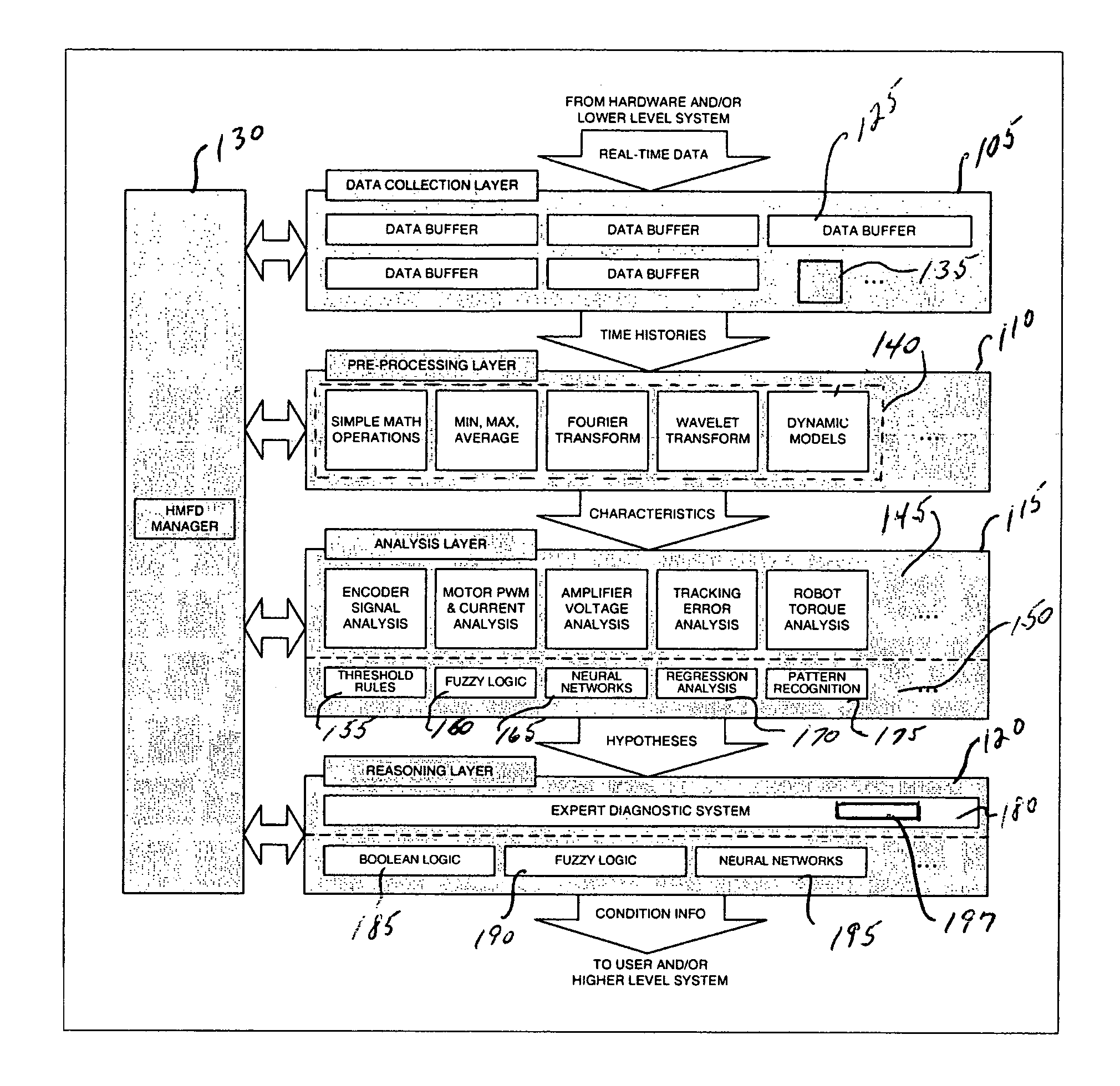
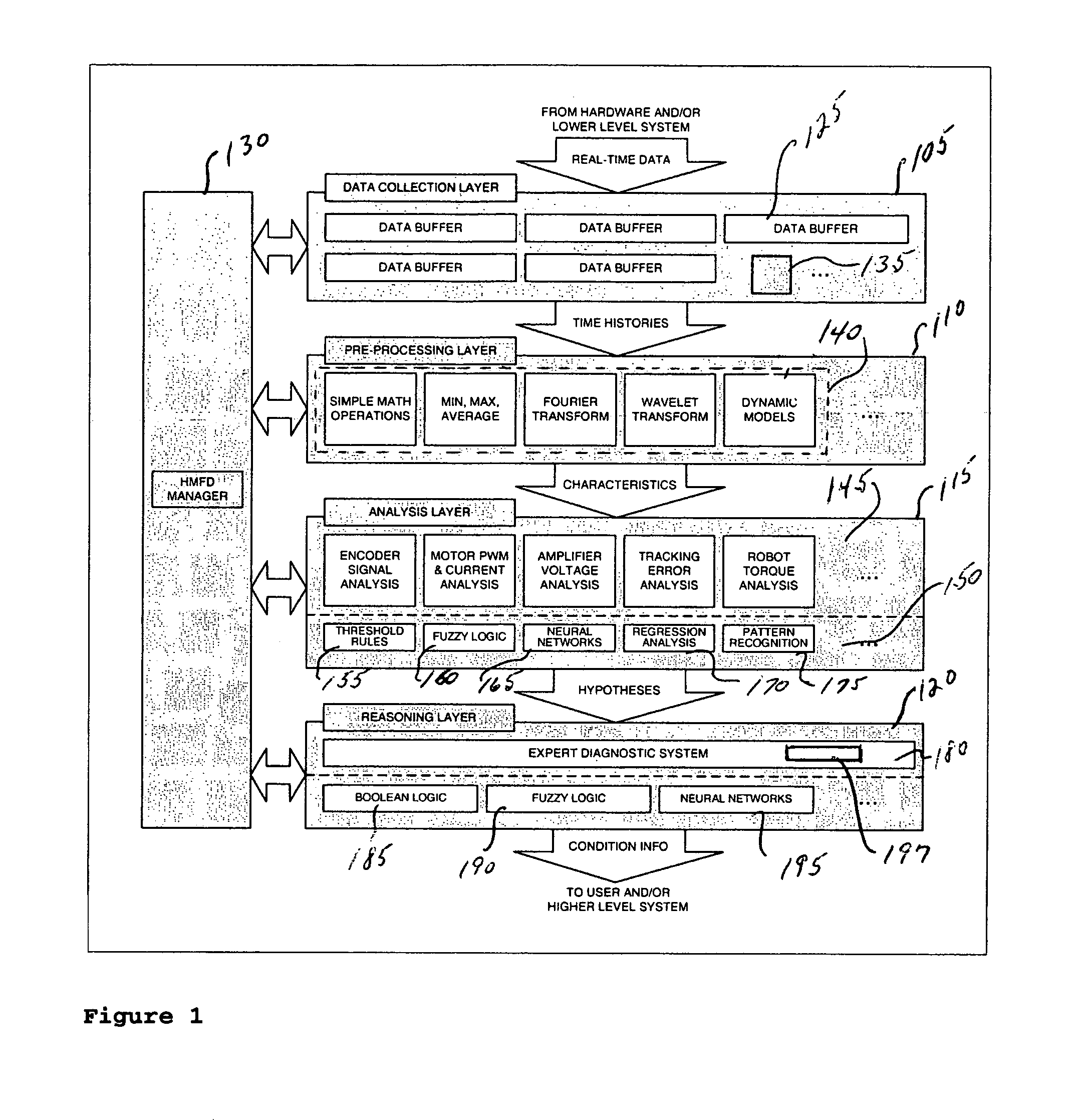
A system for condition monitoring and fault diagnosis includes a data collection function that acquires time histories of selected variables for one or more of the components, a pre-processing function that calculates specified characteristics of the time histories, an analysis function for evaluating the characteristics to produce one or more hypotheses of a condition of the one or more components, and a reasoning function for determining the condition of the one or more components from the one or more hypotheses.

Description

[0001]This application claims the benefit of U.S. Provisional Application No. 60 / 698,521 filed 11 Jul. 2005, which is incorporated by reference herein in its entirety.BACKGROUND[0002]The disclosed embodiments are directed to a condition monitoring and fault diagnosis system.BRIEF DESCRIPTION OF RELATED DEVELOPMENTS[0003]Material damage and unscheduled downtime due to failures of robotic manipulators and other mechatronic devices used in automated manufacturing tools, such as robotized material-handling platforms for production of semiconductor devices, are common problems which often represent a significant cost burden to the end-user of the manufacturing tools.[0004]A number of health-monitoring and fault-diagnostic (HMFD) methods have been developed for industrial, automotive and aerospace applications. The existing systems typically implement fault detection to indicate that something is wrong in the monitored system, fault isolation to determine the exact location of the fault, ...

Claims


Application Information

Patent Timeline
Patent Type & Authority Patents(United States)
IPC IPC(8): G06F11/30
CPCG05B23/0235G07C3/00G06F11/008G16H40/40H01L22/00H01L21/00H01L21/02
Inventor HOSEK, MARTINKRISHNASAMY, JAYPROCHAZKA, JAN
Owner BOOKS AUTOMATION US LLC
Learn More