Radio frequency power amplifier improvements using pre-distortion of an amplitude modulation power supply
a technology of amplitude modulation and power supply, which is applied in the direction of amplitude modulation, amplitude modulation with minimum 3 electrodes, electrical apparatus, etc., can solve the problems of tight channel spacing, narrow channel bandwidth, tight transmission restrictions, etc., and achieve the effect of improving linearity, efficiency, or both, of rf power amplifiers
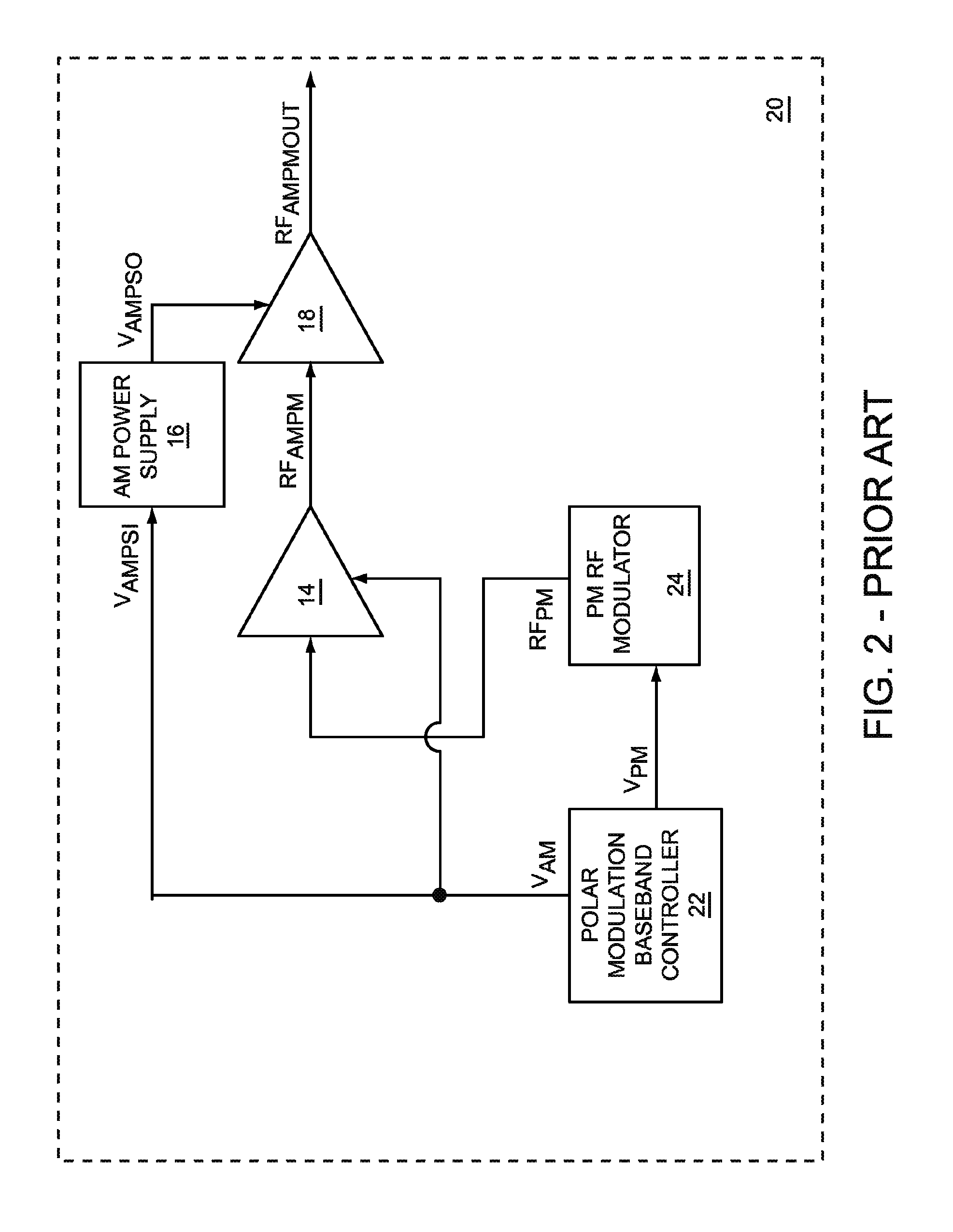
Active Publication Date: 2011-02-08
QORVO US INC
View PDF2 Cites 53 Cited by
- Summary
- Abstract
- Description
- Claims
- Application Information
AI Technical Summary
Benefits of technology
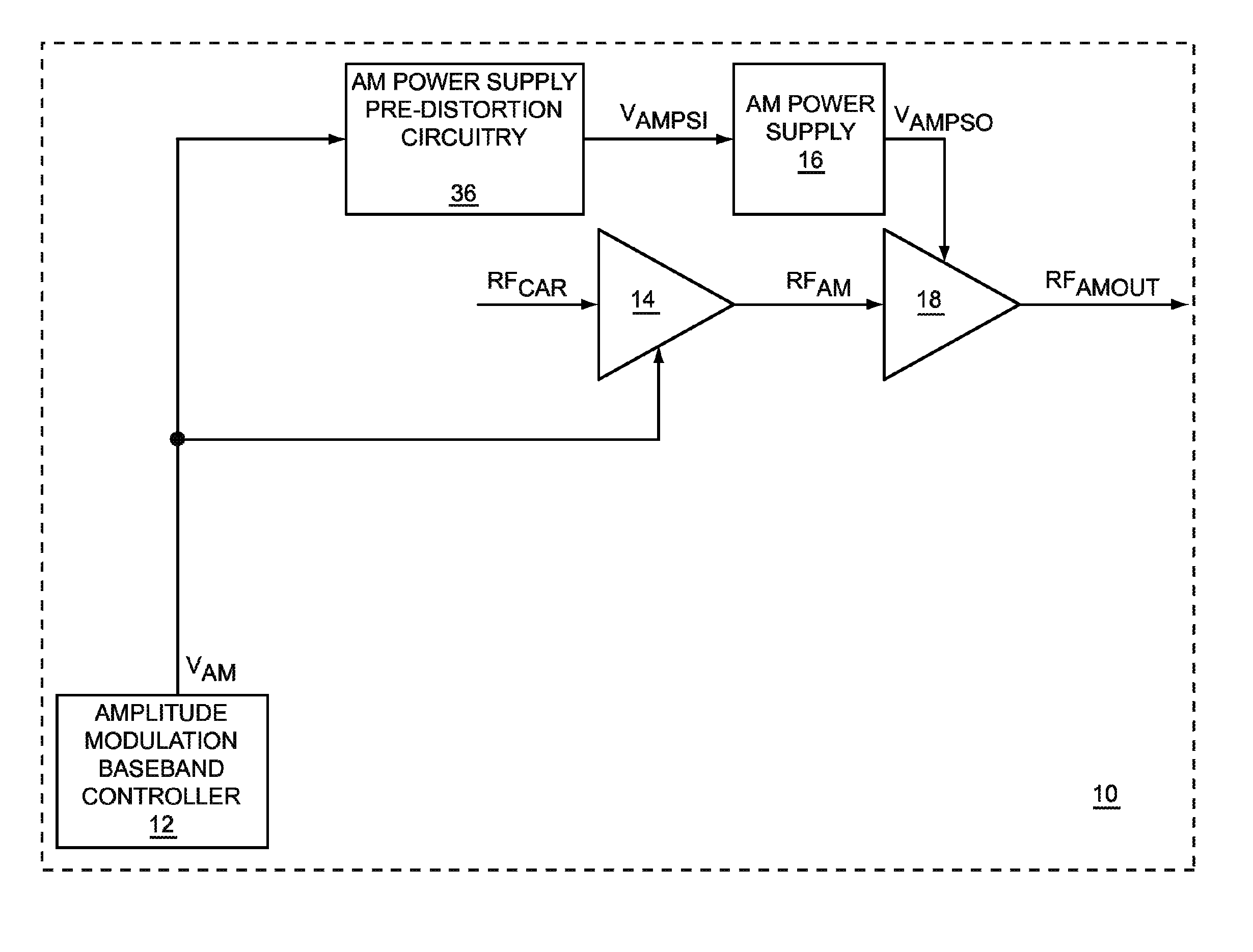
[0006]Embodiments of the present invention include amplitude-modulated or polar-modulated RF power amplifier circuitry, in which an envelope power supply input to an RF power amplifier is powered by a pre-distorted amplitude modulation (AM) power supply. The pre-distorted AM power supply receives an AM signal, which is then pre-distorted and amplified to provide an AM power supply signal to the RF power amplifier. The pre-distortion of the AM signal is used to improve the linearity, the efficiency, or both, of the RF power amplifier. The pre-distortion provides a feed-forward system, which may allow use of a reduced bandwidth pre-distorted AM signal to an AM power supply and a reduced bandwidth AM power supply, which may increase efficiency.
Problems solved by technology
Some of these protocols may have tight channel spacing that require narrow channel bandwidths and tight restrictions on transmissions of spurious RF signals outside a channel's bandwidth.
The RF power amplifier in a wireless portable device may consume a significant portion of the power used by the portable device.
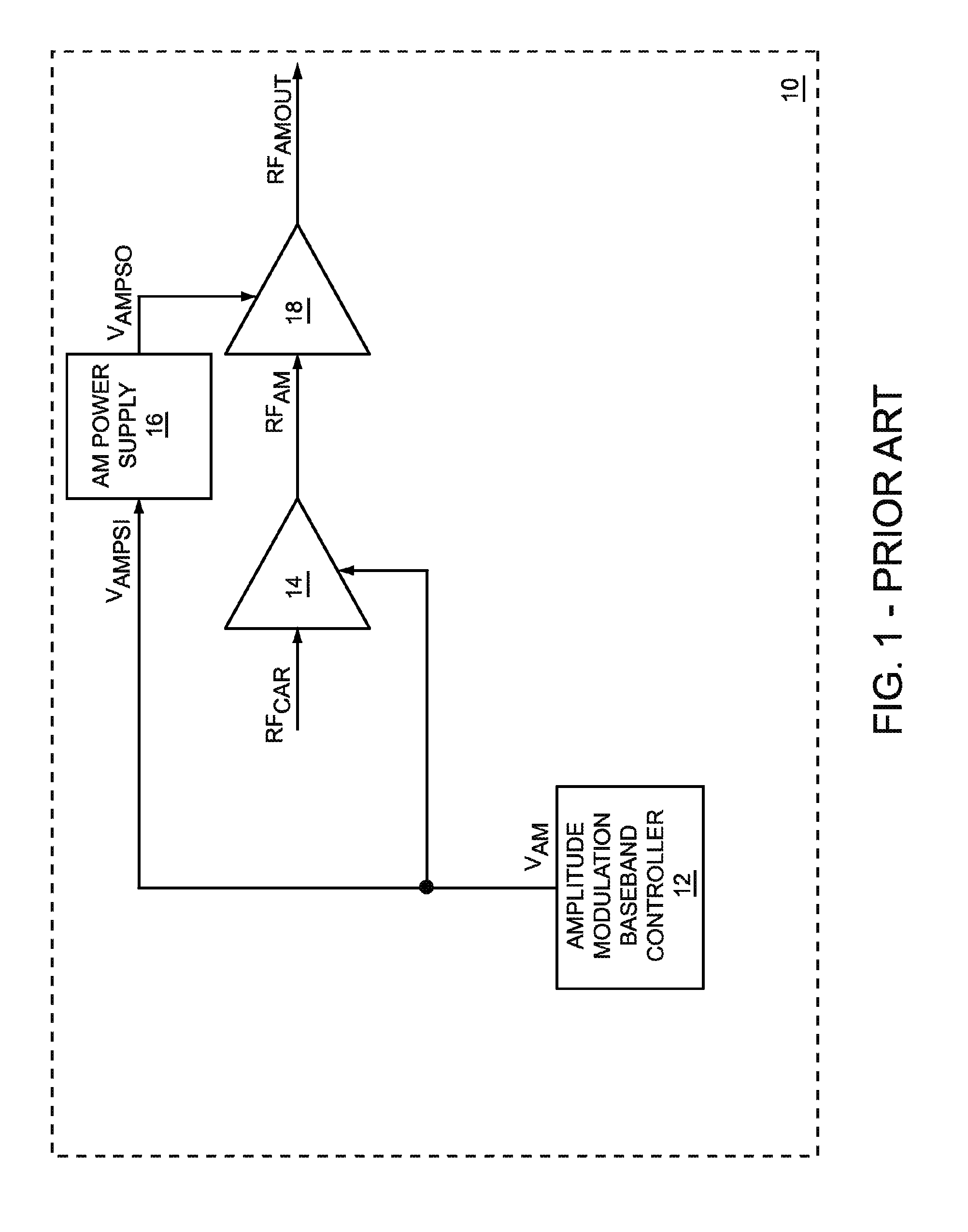
Such an AM power supply may include a switching power supply and a linear power supply to meet bandwidth requirements; however, linear power supplies are typically less efficient than switching power supplies.
Therefore, a 12 megahertz AM power supply may be less efficient than an AM power supply with less bandwidth.
Method used
View moreImage
Smart ImageViewing Examples
Examples
first embodiment
[0030]FIG. 20 is a graph illustrating how the magnitude of the AM power supply input signal relates to the output power of the PA stage, according to the present invention.
third embodiment
[0031]FIG. 21 is a graph illustrating how the magnitude of the AM power supply input signal relates to the output power of the PA stage, according to a second and the present invention.
[0032]FIG. 22 shows an application example of the present invention used in a mobile terminal.
Login to View More PUM
 Abstract
Embodiments of the present invention include amplitude-modulated or polar-modulated radio frequency (RF) power amplifier circuitry, in which an envelope power supply input to an RF power amplifier is powered by a pre-distorted amplitude modulation (AM) power supply. The pre-distorted AM power supply receives an AM signal, which is then pre-distorted and amplified to provide an AM power supply signal to the RF power amplifier. The pre-distortion of the AM signal is used to improve the linearity, the efficiency, or both, of the RF power amplifier. The pre-distortion provides a feed-forward system, which may allow use of a reduced bandwidth pre-distorted AM signal to an AM power supply and a reduced bandwidth AM power supply, which may increase efficiency.
Description
RELATED APPLICATIONS[0001]The present application is related to commonly owned and assigned U.S. patent application Ser. No. 11 / 113,873, filed Apr. 25, 2005, entitled “POWER CONTROL SYSTEM FOR A CONTINUOUS TIME MOBILE TRANSMITTER,” which is hereby incorporated herein by reference in its entirety.FIELD OF THE INVENTION[0002]Embodiments of the present invention relate to amplitude-modulated radio frequency (RF) power amplifiers, including polar-modulated RF power amplifiers that are powered using amplitude-modulated power supplies, which may be used in RF communications systems.BACKGROUND OF THE INVENTION[0003]As technology progresses, portable devices tend to integrate more features. For example, portable devices may include features associated with personal digital assistants (PDAs), cellular telephones, wireless internet access devices, global positioning system (GPS) receivers, and the like. Such portable devices may support one or more wireless communications protocols, such as t...
Claims
Login to View More Application Information
Patent Timeline
 IPC IPC(8): H03C1/00H03C1/02H03C1/06
CPCH03C1/06H03C1/36H03C2200/0083
Inventor KHLAT, NADIMBAUDER, RUEDIGERREED, DAVIDSCOTT, BAKER P.
Owner QORVO US INC
Features
- R&D
- Intellectual Property
- Life Sciences
- Materials
- Tech Scout
- Unparalleled Data Quality
- Higher Quality Content
- 60% Fewer Hallucinations
Learn More Browse by: Latest US Patents, China's latest patents, Technical Efficacy Thesaurus, Application Domain, Technology Topic, Popular Technical Reports.
© 2025 PatSnap. All rights reserved.Legal|Privacy policy|Modern Slavery Act Transparency Statement|Sitemap|About US| Contact US: help@patsnap.com


