Magnetic tunnel junction cell including multiple vertical magnetic domains

a technology of magnetic tunnel junction and magnetic cell, which is applied in the direction of magnetic field-controlled resistors, digital storage, instruments, etc., can solve the problems of double a mjt manufacturing cost, limited mtj device size, and increased data density in the x-y direction, so as to increase the mtj cell density and reduce the device footprint

a technology of magnetic tunnel junction and magnetic cell, which is applied in the direction of magnetic field-controlled resistors, digital storage, instruments, etc., can solve the problems of double a mjt manufacturing cost, limited mtj device size, and increased data density in the x-y direction, so as to increase the mtj cell density and reduce the device footprint

US7885105B2Active Publication Date: 2011-02-08QUALCOMM INC

Image

  • Magnetic tunnel junction cell including multiple vertical magnetic domains
  • Magnetic tunnel junction cell including multiple vertical magnetic domains
  • Magnetic tunnel junction cell including multiple vertical magnetic domains

Examples


Embodiment Construction

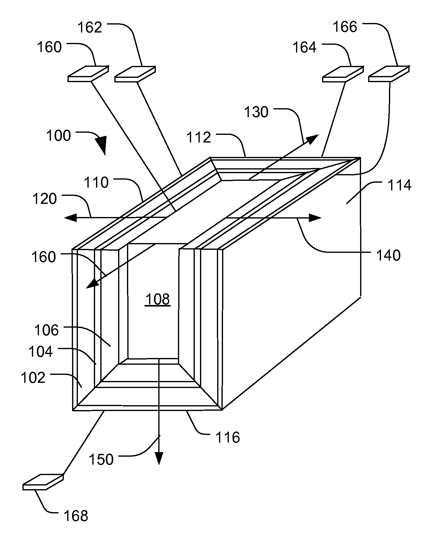
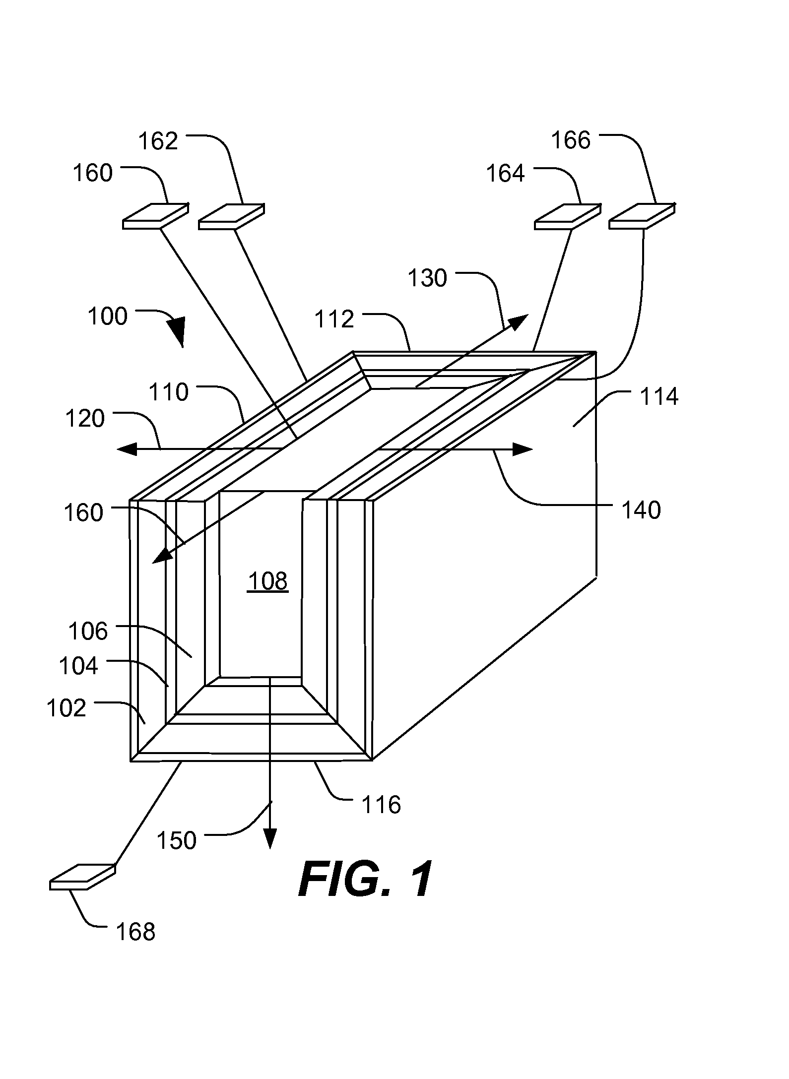
[0054]FIG. 1 is a perspective view of a particular illustrative embodiment of a magnetic tunnel junction (MTJ) cell 100 including multiple vertical magnetic domains that can be used to store multiple digital values. The MTJ cell 100 includes a magnetic tunnel junction (MTJ) stack having a fixed magnetic layer 102, a tunnel junction layer 104, and a free magnetic layer 106 arranged in a substantially rectangular shape. An electrode layer having a first sidewall portion 110, a second sidewall portion 112, a third sidewall portion 114 and a bottom wall portion 116 is electrically and physically coupled to the fixed magnetic layer 102. A center electrode 108 is electrically and physically coupled to the free layer 106. A first terminal structure 160 is coupled to the center electrode 108. A second terminal structure 162 is coupled to the first sidewall 110. A third terminal structure 164 is coupled to the second sidewall 112. A fourth terminal structure 166 is coupled to the third sidew...


PUM

PropertyMeasurementUnit
magneticaaaaaaaaaa
heightaaaaaaaaaa
thicknessaaaaaaaaaa

Abstract

Magnetic tunnel junction cell including multiple vertical domains. In an embodiment, a magnetic tunnel junction (MTJ) structure is disclosed. The MTJ structure includes an MTJ cell. The MTJ cell includes multiple vertical side walls. Each of the multiple vertical side walls defines a unique vertical magnetic domain. Each of the unique vertical magnetic domains is adapted to store a digital value.

Description

I. FIELD[0001]The present disclosure is generally related to a magnetic tunnel junction cell including multiple vertical magnetic domains.II. DESCRIPTION OF THE RELATED ART[0002]In general, widespread adoption of portable computing devices and wireless communication devices has increased demand for high-density and low-power non-volatile memory. As process technologies have improved, it has become possible to fabricate magneto-resistive random access memory (MRAM) based on magnetic tunnel junction (MTJ) devices. Traditional spin torque tunnel (STT) junction devices are typically formed as flat stack structures. Such devices typically have two-dimensional magnetic tunnel junction (MTJ) cells with a single magnetic domain. An MTJ cell typically includes a fixed magnetic layer, a barrier layer (i.e., a tunneling oxide barrier layer, MgO, Al2O3, etc,), and a free magnetic layer, where a bit value is represented by a magnetic field induced in the free magnetic layer and an anti-ferromagn...

Claims


Application Information

Patent Timeline
08 Feb 2011
Publication
US7885105B2
IPC
G11C11/15; H10N50/01; H10N50/10; H10N50/80
CPC
G11C11/16; G11C11/5607; G11C19/0808; H01L43/08; H01L43/12; H01L27/228; Y10S977/935; Y10S977/933
Inventors
LI, XIA; KANG, SEUNG H.