Evaporator and process for fabricating same

a technology of evaporator and process, which is applied in the direction of manufacturing tools, soldering devices, light and heating equipment, etc., can solve the problems of reduced spacing between evaporators, cumbersome fabrication of evaporators, and low brazing efficiency, so as to improve cooling performance, improve work efficiency, and facilitate fabrication

Inactive Publication Date: 2011-02-15
KEIHIN THERMAL TECH CORP
View PDF10 Cites 16 Cited by
  • Summary
  • Abstract
  • Description
  • Claims
  • Application Information

AI Technical Summary

Benefits of technology

[0032]With the evaporators, the inlet header and the outlet header are closed with respective caps each at one end thereof, the cap of the inlet header has a refrigerant inlet, the cap of the outlet header has a refrigerant outlet, and the platelike pipe joint member has a refrigerant inlet portion communicating with the inlet and a refrigerant outlet portion communicating with the outlet and is positioned transversely of and joined to both the inlet header and the outlet header. Accordingly, the pipe joint member has a relatively small thermal capacity, and can be brazed to the inlet header and the outlet header more effectively to ensure facilitated work in fabricating the entire evaporator.
[0044]In the processes for fabricating evaporators, the inlet pipe and the outlet pipe can be brazed to the inlet portion and the outlet portion of the pipe joint member at the same time. The evaporators can therefore be fabricated relatively easily.

Problems solved by technology

However, the inlet-outlet block has a relatively great thermal capacity, and is therefore lower in brazeability, rendering the evaporator cumbersome to fabricate.
The inlet portion and the outlet portion of the pipe joint plate are joined to the inlet pipe and the outlet pipe usually by high-frequency brazing using a high-frequency heating coil provided around these inlet and outlet portions, whereas if the pipe joint plate is restricted in the front-rear dimension, provision of the inlet and outlet portions of approximately the same outside diameter results in a reduced spacing between the inlet and outlet portions, presenting difficulty in fitting the high-frequency heating coil around these portions, making it impossible to automatically carry out the brazing operation and necessitating cumbersome fabrication work.
Furthermore, the reduced spacing between the inlet portion and the outlet portion diminishes the area of brazing joint of the joint plate portion between the inlet and outlet portions and the inlet header or the outlet header, and a faulty joint is likely to occur.
When the brazing joint is faulty, short-circuiting will occur between the inlet header and the outlet header, consequently permitting the refrigerant flowing in through the inlet pipe to flow into the outlet pipe without passing through the heat exchange tubes and failing to contribute to cooling to any extent to entail seriously impaired cooling performance.

Method used


Image

  • Evaporator and process for fabricating same
  • Evaporator and process for fabricating same
  • Evaporator and process for fabricating same

Examples


second embodiment

[0092]FIG. 14 shows the invention. Throughout FIGS. 1 to 14, like parts are designated by like reference numerals.

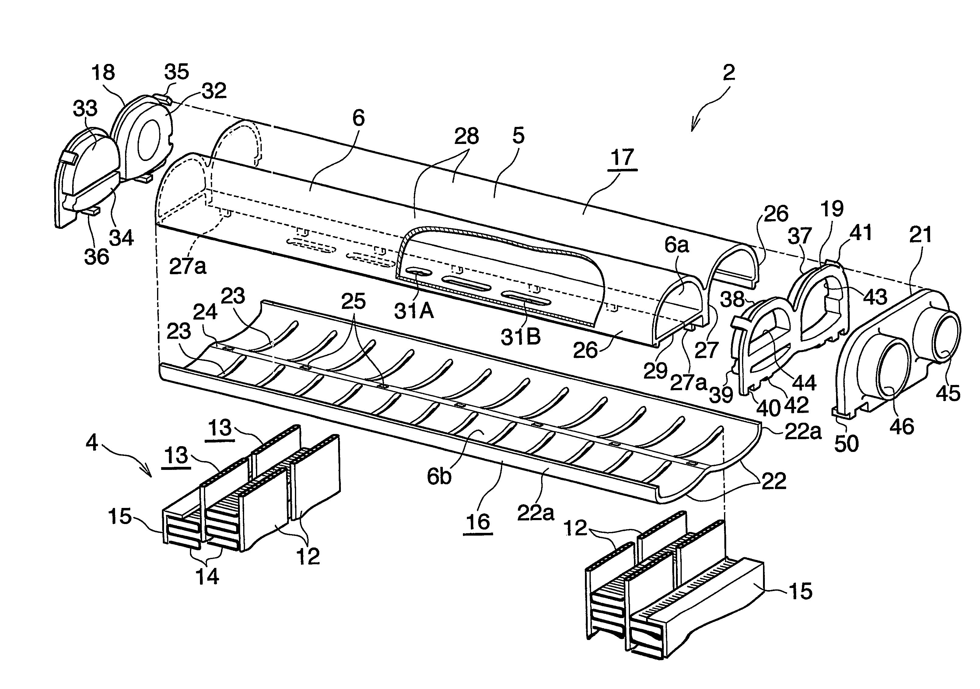
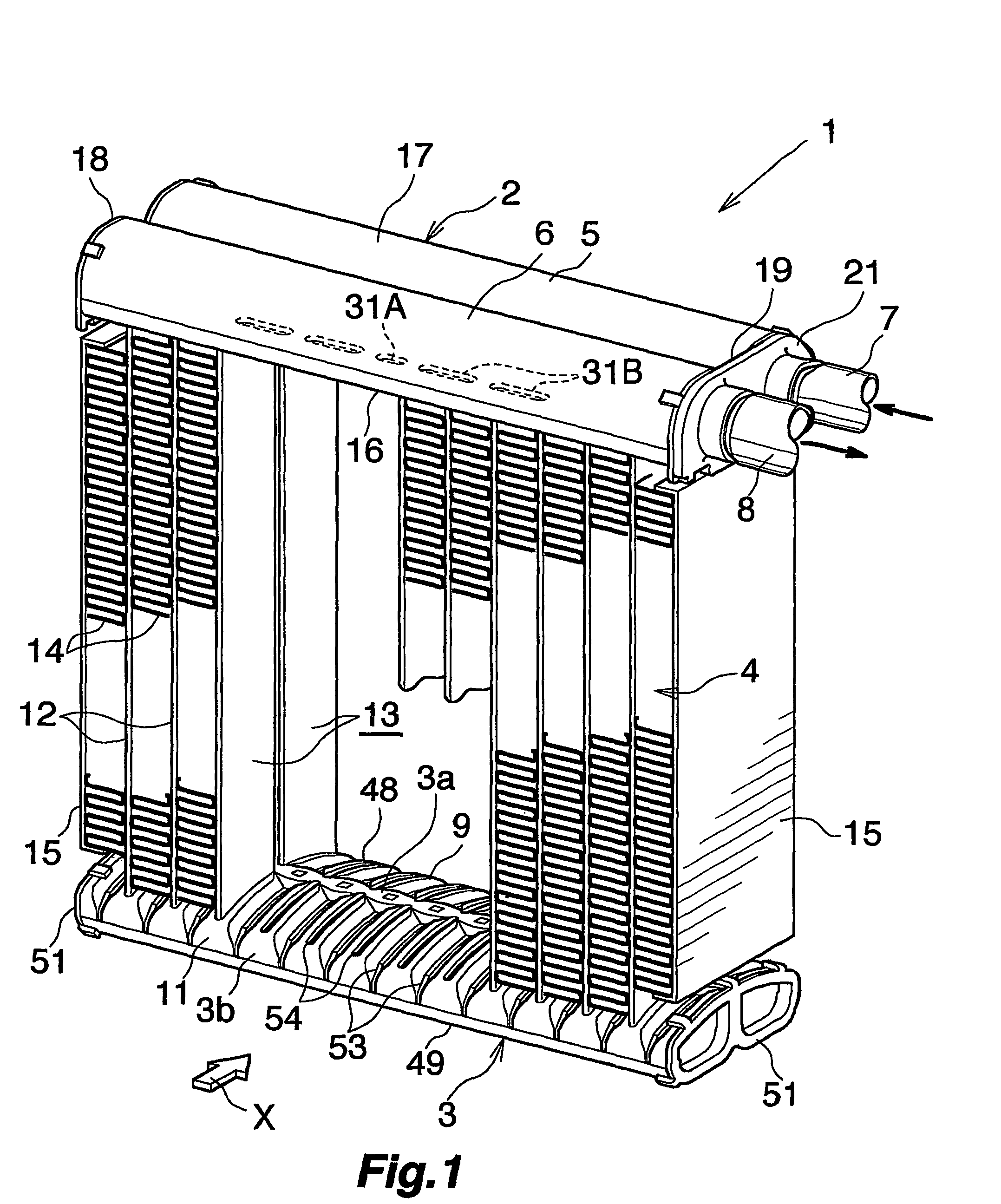
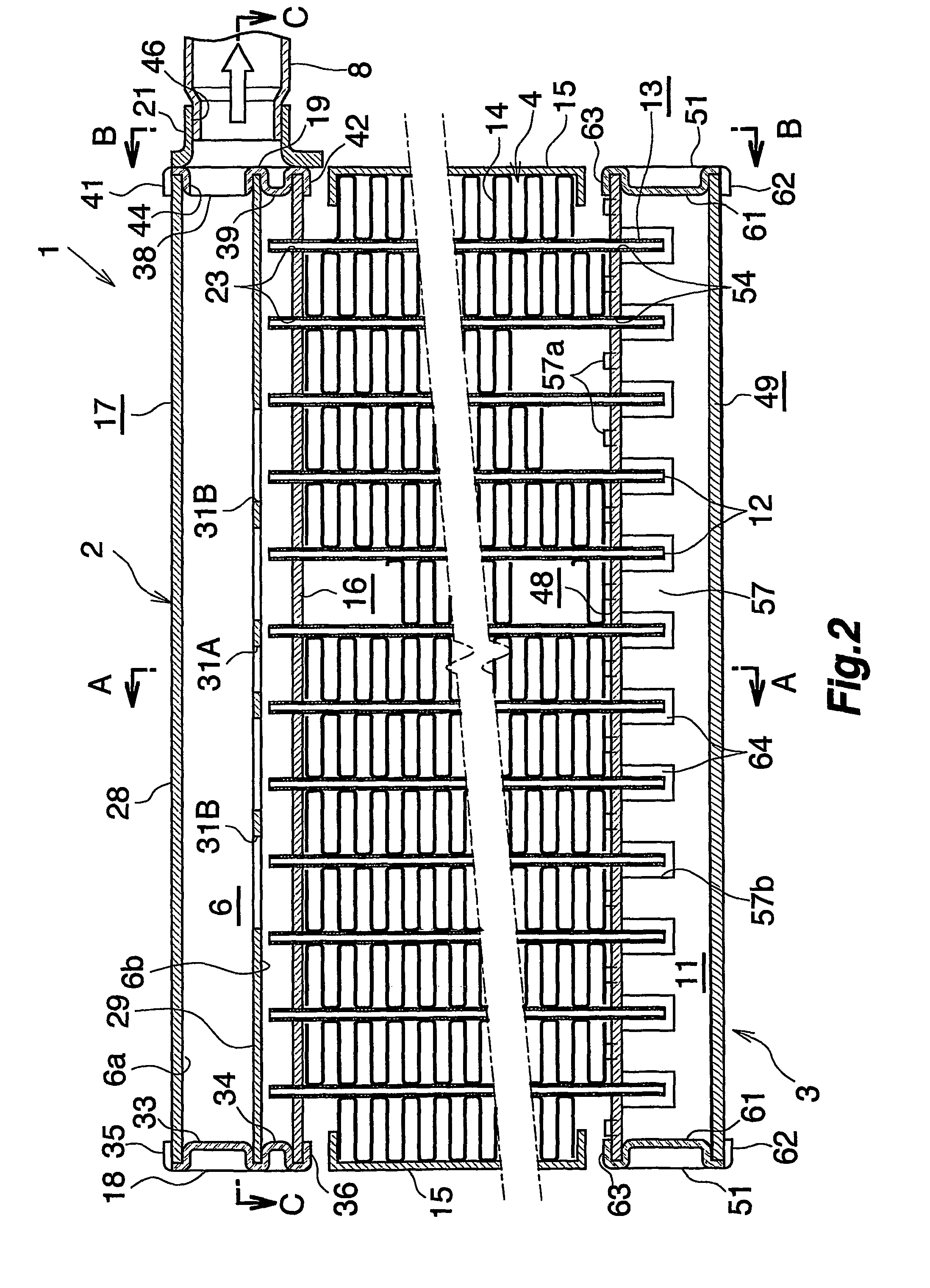
[0093]FIG. 14 shows an evaporator 70 which comprises a refrigerant inlet header 71 and a refrigerant outlet header 72 which are arranged side by side from the front rearward, a first intermediate header 73 provided above the inlet header 71 and spaced apart therefrom, a second intermediate header 74 provided on the left side of the first intermediate header 73, a third intermediate header 75 disposed below and spaced apart from the second intermediate header 74 and positioned on the left side of the inlet header 71, a fourth intermediate header 74 provided alongside the third intermediate header 75 on the rear side thereof and positioned on the left side of the outlet header 72, a fifth intermediate header 77 provided above and spaced apart from the fourth intermediate header 76 and disposed alongside the second intermediate header 74 on the rear side thereof, and a sixt...

first embodiment

[0094]The inlet header 71, outlet header 72, third intermediate header 75 and fourth intermediate header 76 are formed by separating one tank 79 into four portions arranged from the front rearward and from the left to the right. The tank 79 is similar to the refrigerant turn tank 3 of the first embodiment and comprises a first member 48 and a second member 49. The tank 79 differs from turn tank 3 with respect to the following. The tank 79 is divided into a front and a rear space by a partition wall 57 inside the tank, and each of these spaces is divided into a left and a right portion by an aluminum partition plate 81 disposed at the midportion with respect to the left-right direction, whereby four headers 71, 72, 75, 76 are provided. The portion of the partition wall 57 on the right side of the partitions plate 81 has no cutouts 57b, and the inlet header 71 is held out of communication with the outlet header 72. A closing member 51 for the right-end openings has a refrigerant inlet...


PUM

PropertyMeasurementUnit
lengthaaaaaaaaaa
lengthaaaaaaaaaa
diameteraaaaaaaaaa

Abstract

An evaporator includes a refrigerant inlet header and a refrigerant outlet header arranged side by side in a front-rear direction, and a refrigerant circulating passage holding the headers in communication. The inlet and outlet headers are provided with caps forming refrigerant inlet and refrigerant outlet, the caps are joined to a pipe joint member having refrigerant inlet and outlet portions in communication with the refrigerant inlet and outlet, the caps or the pipe joint member is provided with a positioning lug which is projecting from its side edge toward the other one and which is fitted with a positioning recess formed in the other one, and the caps and the pipe joint member have flat surfaces to be contact with each other and are brazed such that the lug is engaged with the recess and that the flat surfaces are in contact with each other.

Description

CROSS REFERENCE TO RELATED APPLICATION[0001]This application is an application filed under 35 U.S.C. §111(a) claiming the benefit pursuant to 35 U.S.C. §119(e) (1) of the filing date of Provisional Application No. 60 / 523,101 filed Nov. 19, 2003 pursuant to 35 U.S.C. §111(b).TECHNICAL FIELD[0002]The present invention relates to evaporators for use in motor vehicle air conditioners which are refrigeration cycles to be installed in motor vehicles.[0003]The term “aluminum” as used herein and in the appended claims includes aluminum alloys in addition to pure aluminum. The downstream side (the direction indicated by the arrow X in FIG. 1, and the right-hand side of FIG. 4) of the air to be passed through the air flow clearance between each adjacent pair of heat exchange tubes will be referred to herein and in the appended claims as “front,” and the opposite side as “rear.” Further the upper, lower, and left- and right-hand sides of FIG. 2 will be referred to as “upper,”“lower,”“left” and...

Claims


Application Information

Patent Timeline
Patent Type & Authority Patents(United States)
IPC IPC(8): F28F9/02F25B39/02F28D1/053F28F9/04
CPCB23K1/0012F25B39/022F28F9/0202F28F9/0246F28F9/0253F28D1/05391B23K2201/14F25B2500/01Y10T29/49396F28F2220/00B23K2101/14F28F9/02F28F9/18F25B39/02
Inventor HIGASHIYAMA, NAOHISA
Owner KEIHIN THERMAL TECH CORP
Why Eureka
Try Eureka