
Apparatus and method for cleaning and decontaminating an air distribution system

a technology of air distribution system and air vacuum cleaner, which is applied in the direction of cleaning equipment, cleaning using liquids, transportation and packaging, etc., can solve the problems of limited effectiveness, inability to remove soot and smoke that continue to permeate the building, and inability to sterilize contaminating substances adhering to the walls of the air distribution system. to achieve the effect of reliable performan

Inactive Publication Date: 2011-02-15
RATLIFF THOMAS R +1
View PDF9 Cites 10 Cited by
  • Summary
  • Abstract
  • Description
  • Claims
  • Application Information

AI Technical Summary

Benefits of technology

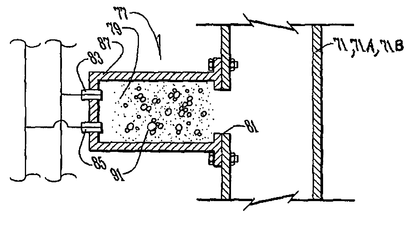
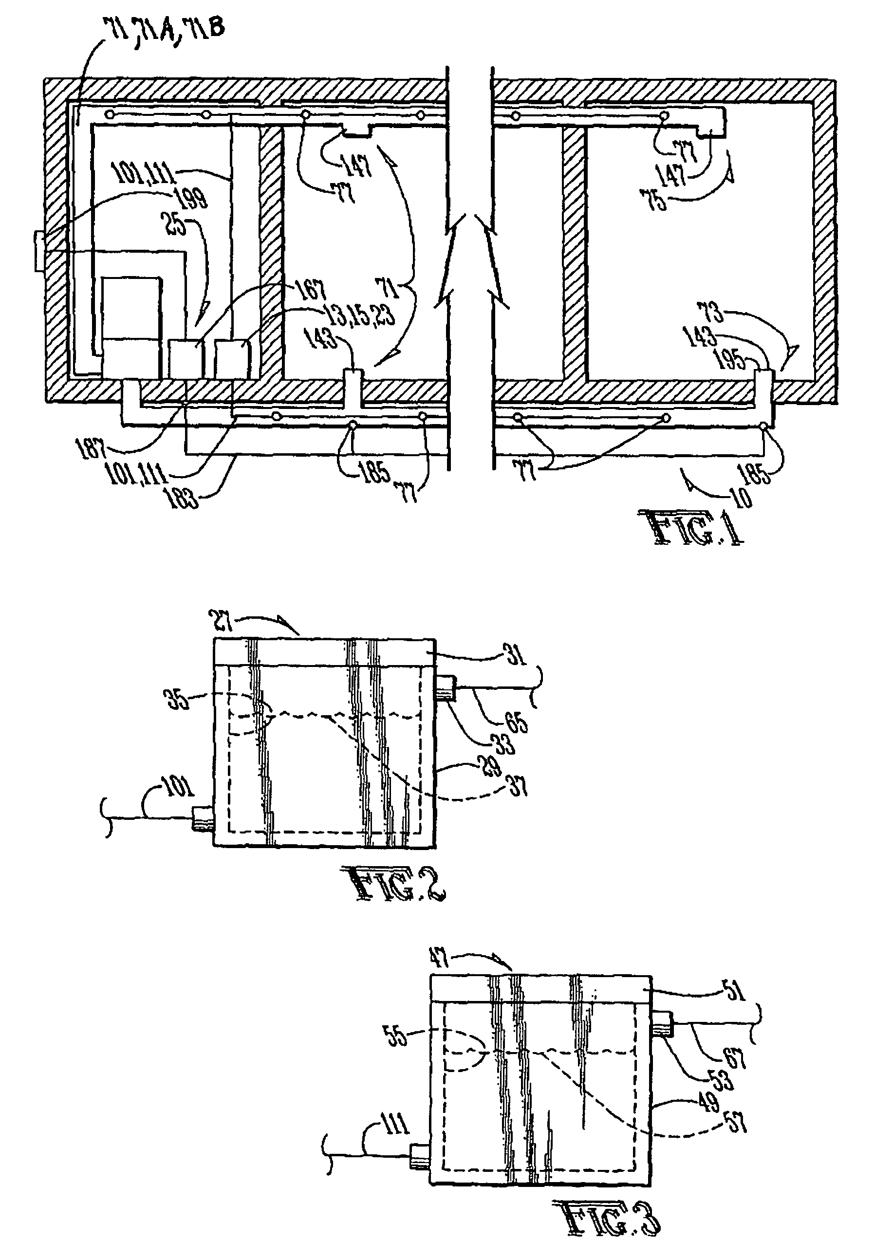
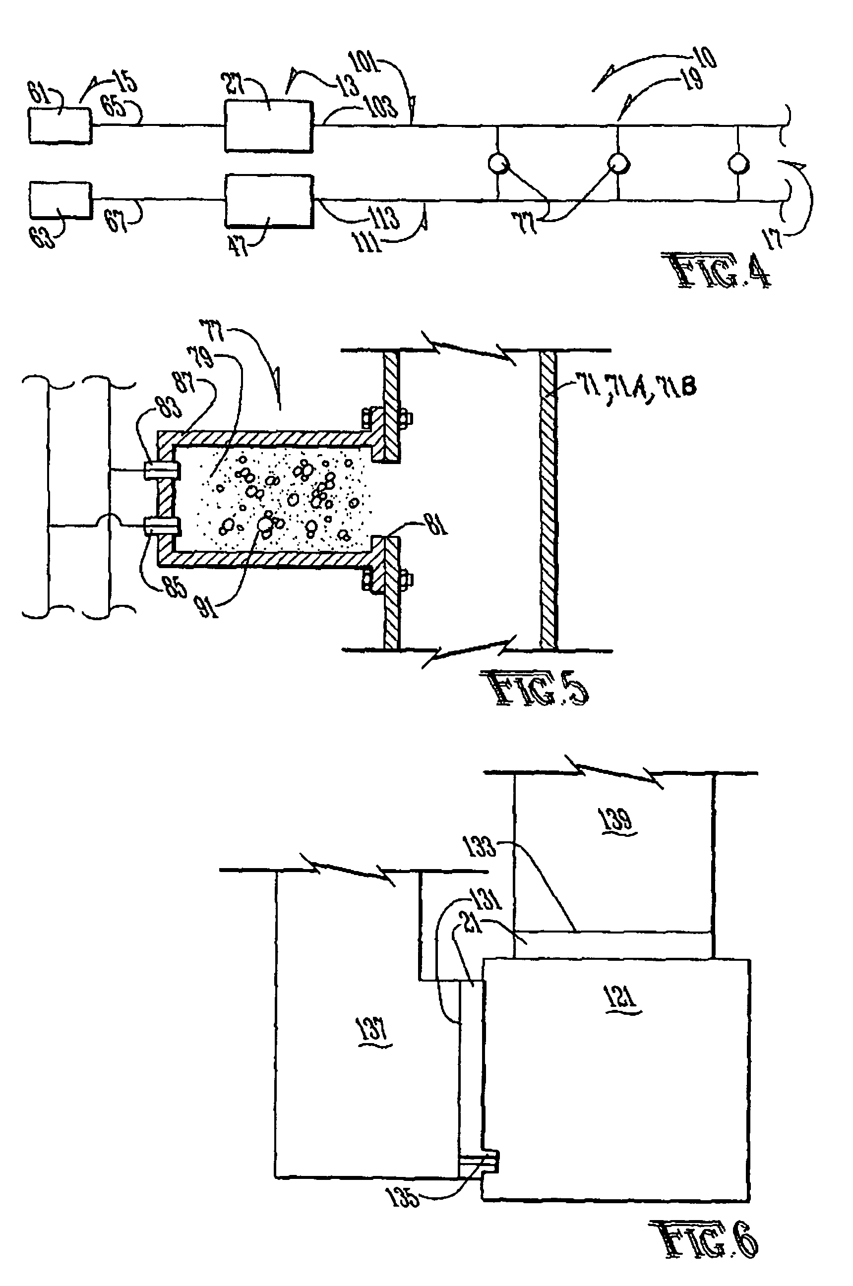
[0013]The principal objects and advantages of the present invention include: providing a system and method for cleaning and decontaminating an air distribution system; providing such a system and method that includes a cleaning agent and an entraining agent; providing such a system and method that utilizes a foam-like substance for cleaning an air distribution system; providing such a system and method that is readily adaptable to a variety of different air distribution systems; and generally providing such a system and method that is reliable in performance, capable of long lasting life, and particularly well adapted for the proposed usages thereof.

Problems solved by technology

However, loose debris that is not spaced in relatively close proximity to the suctioning end of such air vacuuming cleaners may remain in the ductwork to continue contaminating air that flows through the ductwork.
More specifically, although air vacuuming cleaners used for air distribution systems may reach much of the area within the ducts of an air distribution system, the effectiveness thereof is limited by the common existence of abrupt turns in the ducts, changes in duct size to accommodate balanced air flow requirements, changes in duct profile such as from a rectangularly shaped configuration to a cylindrically shaped configuration, and changes from a rigid duct to a flexible duct, etc.
In addition, such air vacuuming cleaners may be largely ineffective for removing contaminants and for sterilizing contaminating substances adhering to the walls of the air distribution system, such as toxic chemical or biological substances, for example.
Also, it is well-known that after a fire, such as in a home or in a place of business having a forced-air heating and ventilating system, it is difficult if not impossible to remove the soot and pungent smell of smoke that continues to permeate the building interior, much of which emanates from heat ducts of the air distribution system.
The aforementioned air vacuuming cleaners are largely ineffective for removing such post-fire soot and sources of obtrusive odors.
Also, various offensive odors may be generated while an airliner is in flight wherein such odors are circulated through the passageways of an air distribution system of the airliner.
Many times, the removal of such odors may be quite difficult and / or time-consuming.
As a result, either the airliner may need to be grounded until the odors can be adequately removed, or the passengers of the continuing flights of that aircraft may have no choice but to endure those odors for the duration of their flight.
Even if air vacuuming cleaners could remove all of such contamination, which is extremely doubtful, the ability to reliably filter absolutely all of such contamination from air exhausted by such air vacuuming cleaners is highly questionable.

Method used


Image

  • Apparatus and method for cleaning and decontaminating an air distribution system
  • Apparatus and method for cleaning and decontaminating an air distribution system
  • Apparatus and method for cleaning and decontaminating an air distribution system

Examples


Embodiment Construction

[0029]As required, embodiments of the present invention are disclosed herein, however, it is to be understood that the disclosed embodiments are merely exemplary of the invention, which may be embodied in various forms. Therefore, specific structural and functional details disclosed herein are not to be interpreted as limiting, but merely as a basis for claims and as a representative basis for teaching one skilled in the art to variously employ the present invention in virtually any appropriately detailed structure.

[0030]The present invention is easily adaptable for installation and use in various types of building structures such as commercial buildings, residential dwellings and housing, hospitals, and high rise apartments for example, and for installation and use in various types of non-building structures such as airplanes, cruise ships, trains, subways, and cars for example, or for any other structure or mode of transportation that has an air distribution system. The self-clean...


PUM


Abstract

An apparatus for cleaning and decontaminating an air distribution system includes a sources separately containing a first fluid and a second fluid, a pressurizing system for separately pressurizing the first and second fluids, a distribution subsystem for separately conveying the first and second fluids to a plurality of injectors that convert the first and second fluids into a foam-like substance before injecting the foam-like substance into the air distribution system. The apparatus includes a control system for controlling the pressure and flow rate of the first and second fluids, and a system for removing the foam-like substance from the air distribution system after the foam-like substance has cleaned and decontaminated the air distribution system. A method for cleaning and decontaminating an air distribution system is also disclosed.

Description

CROSS REFERENCE TO RELATED APPLICATIONS[0001]This patent application is a continuation of U.S. patent application Ser. No. 12 / 319,199, filed Jan. 2, 2009 and now U.S. Pat. No. 7,617,829, issued Nov. 17, 2009; which is a divisional of U.S. patent application Ser. No. 10 / 965,396, filed Oct. 15, 2004 and now U.S. Pat. No. 7,588,037, issued Sep. 15, 2009.BACKGROUND OF THE INVENTION[0002]1. Field of the Invention[0003]The present invention is related to cleaning equipment and, more specifically without limitation, to cleaning and decontaminating equipment for heating, ventilating and air-conditioning (HVAC) systems.[0004]2. Discussion of the Related Art[0005]More and more people are becoming aware that allergies and various respiratory ailments are exacerbated by various air-entrained particulate substances. It is being increasingly recognized that a common source for such particulate substances is settlement, decaying insects, mold, and other debris and pollutants that accumulate over t...

Claims


Application Information

Patent Timeline
Patent Type & Authority Patents(United States)
IPC IPC(8): B08B9/02
CPCA47L7/0038A47L7/0042B01F3/04446B01F5/0696B01F5/0697B08B9/00B08B9/027B01F23/235B01F25/45242B01F25/45241
Inventor RATLIFF, THOMAS R.LATHROP, DARREL
Owner RATLIFF THOMAS R
Learn More