Microprocessor programmable clock calibration system and method

a microprocessor and clock technology, applied in the direction of instruments, digital transmission, generating/distributing signals, etc., can solve the problems of high accuracy oscillation clocks, require external components, and require significant power, and achieve low power, high clock accuracy, and reduce noise and emi

Active Publication Date: 2011-02-15
ANALOG DEVICES INC
View PDF13 Cites 16 Cited by
  • Summary
  • Abstract
  • Description
  • Claims
  • Application Information

AI Technical Summary

Benefits of technology

It is a further object of this invention to provide such an improved microprocessor method and system with programmable clock calibration which enables high clock accuracy with low power.
It is a further object of this invention to provide such an improved microprocessor method and system with programmable clock calibration which reduces noise and EMI because the higher accuracy, higher power reference oscillator clock runs for only limited periods of time.
It is a further object of this invention to provide such an improved microprocessor method and system with programmable clock calibration which enables a low accuracy clock to be used in high accuracy applications.

Problems solved by technology

High accuracy oscillation clocks come with a certain cost.
They require external components including e.g., resistors, capacitors, crystal oscillators and require significant power.
High accuracy oscillator clocks on sub-micron CMOS have high power budgets and are prone to electronic noise and EMI generation: the high current needs of high accuracy oscillator clocks in sub-micron CMOS causes electrical noise and driving clock signals to external pins radiates EMI.
CMOS based oscillator clocks with better than 3% accuracy have high power consumption especially at lower geometries e.g. 0.25μ and external crystals running continuously can cause electrical noise and EMI.

Method used


Image

  • Microprocessor programmable clock calibration system and method
  • Microprocessor programmable clock calibration system and method
  • Microprocessor programmable clock calibration system and method

Examples


Embodiment Construction

Aside from the preferred embodiment or embodiments disclosed below, this invention is capable of other embodiments and of being practiced or being carried out in various ways. Thus, it is to be understood that the invention is not limited in its application to the details of construction and the arrangements of components set forth in the following description or illustrated in the drawings. If only one embodiment is described herein, the claims hereof are not to be limited to that embodiment. Moreover, the claims hereof are not to be read restrictively unless there is clear and convincing evidence manifesting a certain exclusion, restriction, or disclaimer.

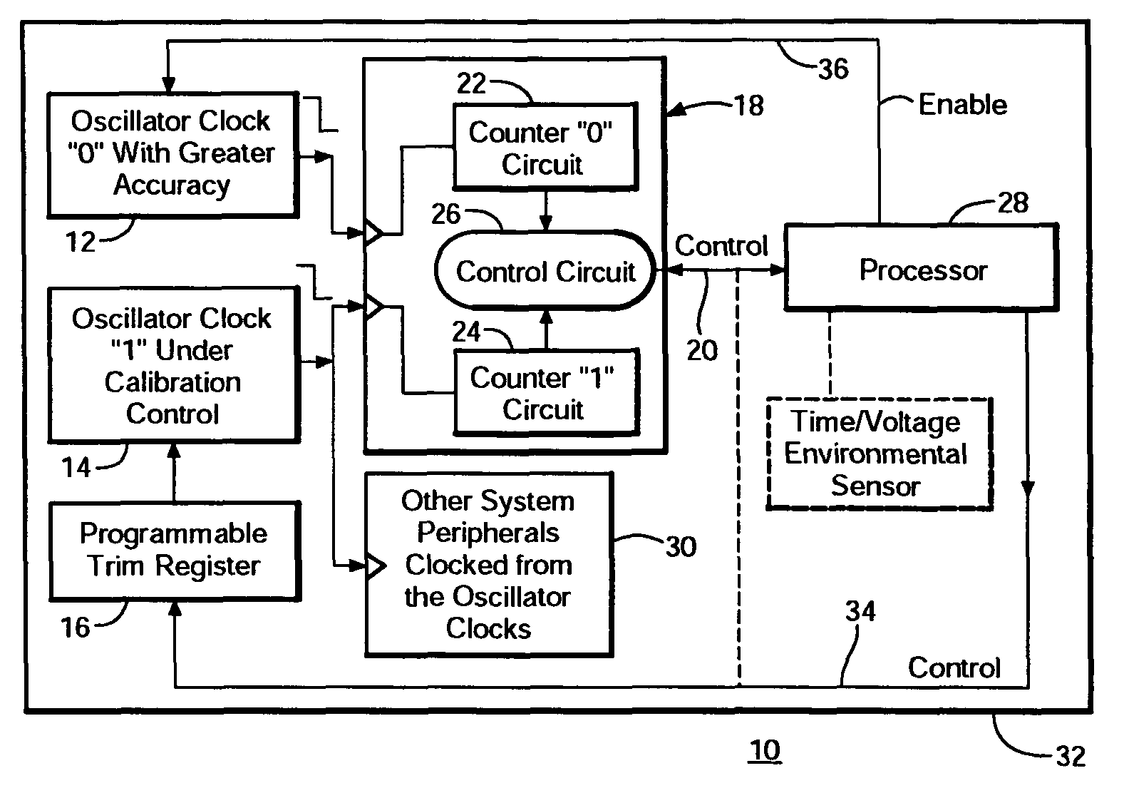
One embodiment of a microprocessor programmable clock calibration system 10 is shown in FIG. 1 as including a higher accuracy, higher power, oscillator “0”, 12 and a lower power, lower accuracy oscillator clock “1”, 14 which is calibratable. The frequency of clock 14 is controlled by programmable trim register 16. Calibration con...


PUM


Abstract

A microprocessor programmable clock calibration device compares, in response to a calibration command from a programmable processor, turns on a normally off reference oscillator clock, compares the frequency of the reference oscillator clock with the frequency of a calibratable oscillator clock, turns off the reference oscillator clock and adjusts, in response to a difference in those frequencies, the frequency of the calibratable oscillator clock towards that of the reference oscillator clock.

Description

FIELD OF THE INVENTIONThis invention relates to a microprocessor clock calibration system and method.BACKGROUND OF THE INVENTIONMicroprocessor systems require highly accurate oscillation clocks especially in communication applications. High accuracy oscillation clocks come with a certain cost. They require external components including e.g., resistors, capacitors, crystal oscillators and require significant power. High accuracy oscillator clocks on sub-micron CMOS have high power budgets and are prone to electronic noise and EMI generation: the high current needs of high accuracy oscillator clocks in sub-micron CMOS causes electrical noise and driving clock signals to external pins radiates EMI. CMOS based oscillator clocks with better than 3% accuracy have high power consumption especially at lower geometries e.g. 0.25μ and external crystals running continuously can cause electrical noise and EMI. One attempt to address this problem includes using a reference signal and a calibrati...

Claims


Application Information

Patent Timeline
Patent Type & Authority Patents(United States)
IPC IPC(8): G06F1/12
CPCG06F1/04H03L1/00H03L7/00H04L7/0004
Inventor BRADLEY, SHAUNHEFFERNAN, KIERANTANSLEY, TOMASLING, YANG
Owner ANALOG DEVICES INC
Why Eureka
Try Eureka