Power amplifier, method for controlling power amplifier, and wireless communication apparatus

a power amplifier and wireless communication technology, applied in amplifier combinations, amplifier modifications to reduce non-linear distortion, gain control, etc., can solve the problems of reducing the saturated output power affecting the linearity of a power amplifier class ab, and difficulty in achieving low power consumption, so as to achieve the effect of reducing the saturated output power and high-efficiency low distortion characteristics

Inactive Publication Date: 2011-02-22
SHARP KK
View PDF16 Cites 12 Cited by
  • Summary
  • Abstract
  • Description
  • Claims
  • Application Information

AI Technical Summary

Benefits of technology

[0036]The present invention is made in view of the problem. An object of the present invention is to provide a power amplifier that can reduce the possibility that the saturated output power is reduced due to the fact that the power amplifier should have a highly efficient low-distortion characteristic.
[0039]According to the arrangement, an output impedance of the output block bias circuit is set by the output block distortion compensating circuit to such a value that a saturated output power of the output block bipolar transistor of the output block is maximized, i.e., the output impedance is set to a sufficiently low value. This makes it possible to suppress a decrease in saturated output power of the output block bipolar transistor.
[0040]Thus, decrease in saturated output power of the power amplifier is suppressed. In addition, an output impedance of the preceding block bias circuit is adjusted. The output impedance of the preceding block bias circuit is set so that an operating voltage becomes such a voltage that a distortion of an output power of the whole power amplifier with respect to an input power is canceled out by utilizing an amplitude distortion characteristic of an output power of the output block bipolar transistor with respect to an input power and an amplitude distortion characteristic of the preceding block bipolar transistor. This makes it possible to realize a highly efficient low-distortion power amplifier as is the case with a power amplifier according to a conventional art, and suppression of a decrease in saturated output power of the highly efficient low-distortion power amplifier.

Problems solved by technology

Therefore, a wireless communication apparatus having a Class A power amplifier consumes a large amount of power, thereby having a difficulty in achieving low power consumption.
This greatly impairs linearity of the Class AB power amplifier, in contrast to a Class A power amplifier.
Unfortunately, the problem arises that it is likely to decrease the saturated output power of a power amplifier, in a case where the power amplifier is configured based on the disclosure of Patent Literature 1 so as to have a highly efficient low-distortion characteristic.
As a result, a gain of the output block of the power amplifier decreases, thereby causing a decrease in saturated output power.
Therefore, it is difficult to simultaneously optimize a saturated output power and an amplitude distortion.

Method used


Image

  • Power amplifier, method for controlling power amplifier, and wireless communication apparatus
  • Power amplifier, method for controlling power amplifier, and wireless communication apparatus
  • Power amplifier, method for controlling power amplifier, and wireless communication apparatus

Examples


first embodiment

[0104]The below describes a simulation circuit of a power amplifier in accordance with one embodiment of the present invention, and simulated results of output power characteristics measured by use of the simulation circuit.

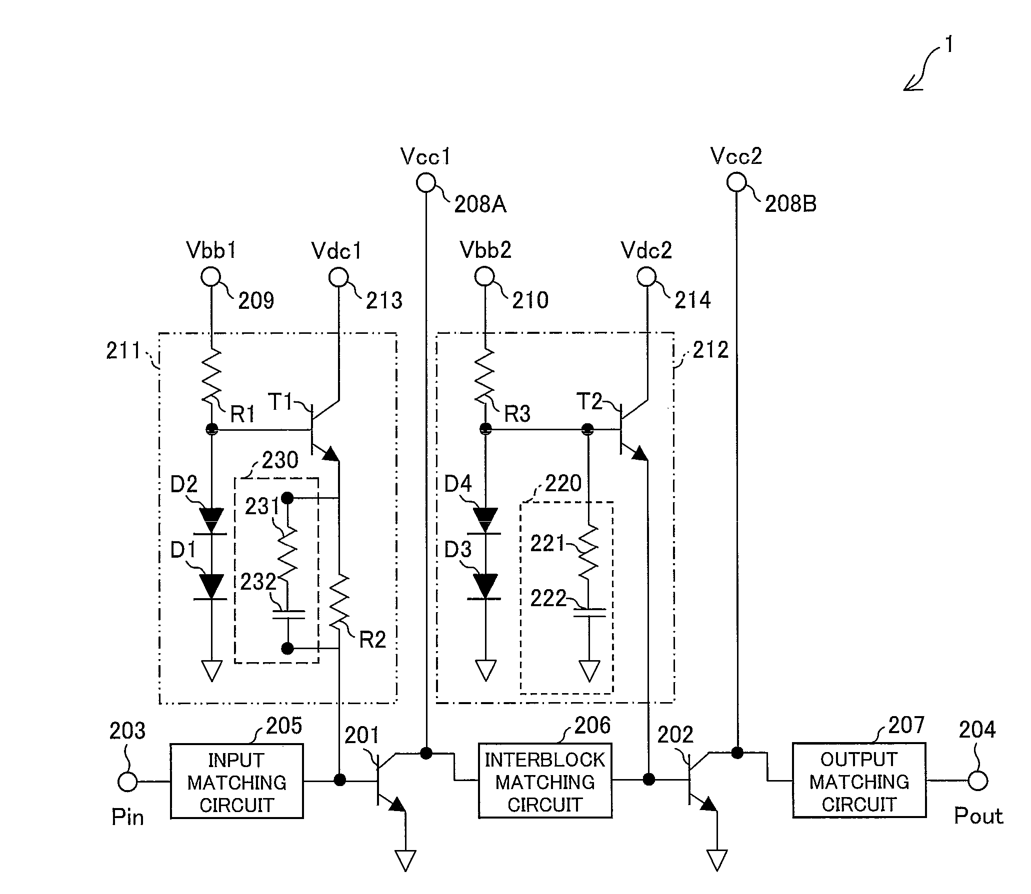
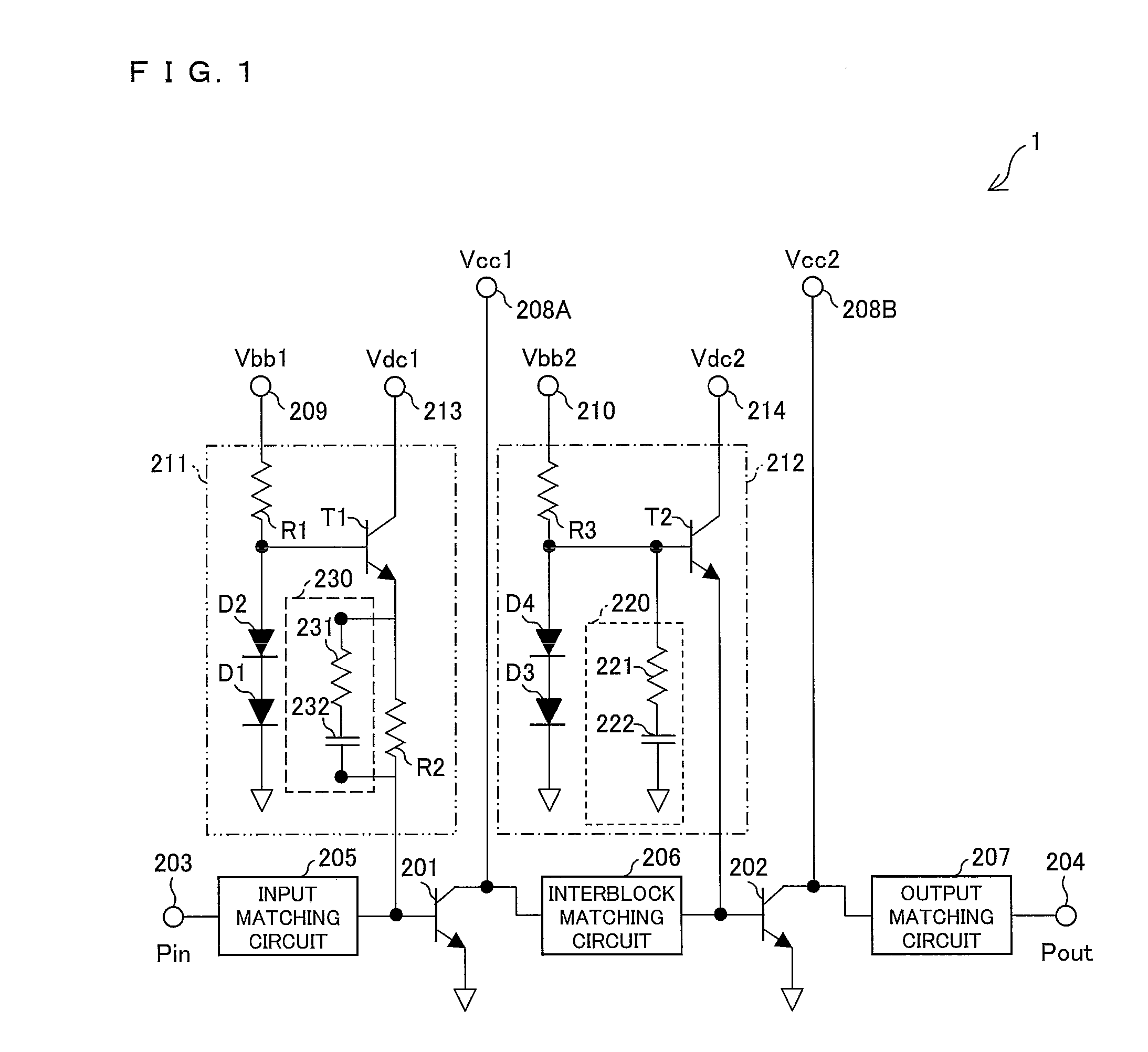
[0105]FIG. 1 is a circuit diagram illustrating a configuration of the simulation circuit of the power amplifier in accordance with the one embodiment of the present invention.

[0106]As illustrated in FIG. 1, a power amplifier 1 of the present embodiment can be realized by a simulation circuit in which a distortion compensating circuit 230 is added to a bias circuit 211 in an arrangement of a simulation circuit of the conventional power amplifier illustrated in FIG. 9. The distortion compensating circuit 230 is a series circuit composed of a resistor 231 and a capacitor 232. As illustrated in FIG. 1, the series circuit is preferably connected in parallel with a resistor R2.

[0107]The power amplifier 1 illustrated in FIG. 1 is arranged such that the distortion compen...

second embodiment

[0121]The below describes a simulation circuit of a power amplifier in accordance with another embodiment of the present invention, and simulated results of output power characteristics measured by use of the simulation circuit.

[0122]FIG. 3 is a circuit diagram illustrating a configuration of the simulation circuit of the power amplifier in accordance with the another embodiment of the present invention.

[0123]In addition to the circuit configuration of a power amplifier 1 illustrated in FIG. 1, a power amplifier 2 further includes, in a bias circuit 212, (i) a distortion compensating circuit (output block distortion compensating circuit) 240 which is a series circuit composed of a resistor 241 and a capacitor 242 and (ii) a resistor R12 (output block base ballast resistor) (see FIG. 3). The resistor R12 is provided between a base terminal of a transistor 202 and an emitter terminal of a bipolar transistor T2. The resistor R12 is a ballast resistor for preventing thermal runaway of t...

third embodiment

[0139]FIG. 7 is a circuit block diagram illustrating a circuit configuration of a wireless communication apparatus having a power amplifier of the present invention.

[0140]A wireless communication apparatus 30 illustrated in FIG. 7 includes an antenna (transmitting antenna) 31 for outputting outside an output signal (output power Pout) amplified by a power amplifier 36, an a antenna duplexer 32 connected to the antenna 31, a receiving circuit 33 connected to an output terminal of the antenna duplexer 32, a transmitting circuit 34 connected to an input terminal of the antenna duplexer 32, a circuit block 35, including a modem, a baseband circuit, and other circuit components, for receiving a received signal from the receiving circuit 33, a circuit 37 (hereinafter, referred to as preceding circuit 37), followed by a power amplifier 36, for receiving a transmitted signal from the circuit block 35, and the power amplifier 36 that amplifies a transmitted signal supplied from the preceding...


PUM


Abstract

A power amplifier includes: a distortion compensating circuit that causes a bias circuit to have an output impedance so that a subsequent block bipolar transistor for signal amplification-use has a maximized saturated output power; and a distortion compensating circuit that causes a bias circuit to have an output impedance so that a distortion of an output power of the power amplifier 1 with respect to an input power is canceled by a distortion characteristic of an output power with respect to an input power of the subsequent block bipolar transistor for signal amplification-use which has a maximized saturated output power and a distortion characteristic of an output power with respect to an input power of the preceding block bipolar transistor for signal amplification-use. This makes it possible to provide a power amplifier that allows reduction in saturated output power brought by realization of a highly efficient low-distortion power amplifier.

Description

[0001]This Nonprovisional application claims priority under 35 U.S.C. §119(a) on Patent Application No. 2008-239829 filed in Japan on Sep. 18, 2008, the entire contents of which are hereby incorporated by reference.TECHNICAL FIELD[0002]The present invention relates to (i) a power amplifier that efficiently amplifies a modulated wave of a digital signal, while keeping distortion low, in a wireless communication apparatus such as a mobile terminal, (ii) a method for controlling the power amplifier, and (iii) a wireless communication apparatus.BACKGROUND ART[0003]For example, a power amplifier used in a wireless communication apparatus, such as a mobile terminal, on a transmitting side handles signals (i.e., modulated waves of digital signals) that have been subjected to digital modulation such as amplitude modulation or phase modulation. As such, the power amplifier requires improvement in linearity of an output signal, i.e., a reduction in distortion.[0004]In addition, the power ampl...

Claims


Application Information

Patent Timeline
Patent Type & Authority Patents(United States)
IPC IPC(8): H03G3/30H03F3/04
CPCH03F1/0211H03F1/0261H03F3/245H03F1/32H03F2200/411H03F2200/18
Inventor ASANO, HIROYUKI
Owner SHARP KK
Why Eureka
Try Eureka