Linear displacement sensor using a position sensitive photodetector

a position sensitive, sensor technology, applied in the direction of converting sensor output, measurement devices, instruments, etc., can solve the problems of limiting the linearity and accuracy of the signal of the optical position sensing device such as those outlined above, and the distribution of light within the detected light spot will have a corresponding non-uniformity, so as to minimize the intensity variation and maximize the signal

Inactive Publication Date: 2011-02-22
MITUTOYO CORP
View PDF8 Cites 40 Cited by
  • Summary
  • Abstract
  • Description
  • Claims
  • Application Information

AI Technical Summary

Benefits of technology

[0010]In various embodiments, the measuring range spans a dimension MR along the measuring axis direction, and the measuring spot is formed by of rays originating from a portion of the diffuse light source spanning a light contribution dimension DLS along the measuring axis direction. In some embodiments, it may be advantageous if the dimension DLS is greater than 0.5 times the dimension MR, or 1.0 times the dimension MR, or more in some embodiments. Alternatively, in some embodiments, the light contribution dimension DLS has a value of at least 2*DP2, or 4*DP2, or more in some embodiments. When the dimension DLS is larger, more light is concentrated into measuring spot, which helps maximize the signal and minimize intensity variations within the measurement spot 130 as a function of measurement position.

Problems solved by technology

Briefly stated, the prior art for optical position sensing devices such as those outlined above does not adequately consider variations in the angular intensity distribution of light from the light source.
In addition, when the source light has a non-uniform angular intensity distribution, the distribution of light within the detected light spot will have a corresponding non-uniformity that varies depending on the position of the aperture along the measuring axis.
These effects have introduced undesirable errors in prior art devices, limiting their signal linearity and accuracy.

Method used


Image

  • Linear displacement sensor using a position sensitive photodetector
  • Linear displacement sensor using a position sensitive photodetector
  • Linear displacement sensor using a position sensitive photodetector

Examples


first embodiment

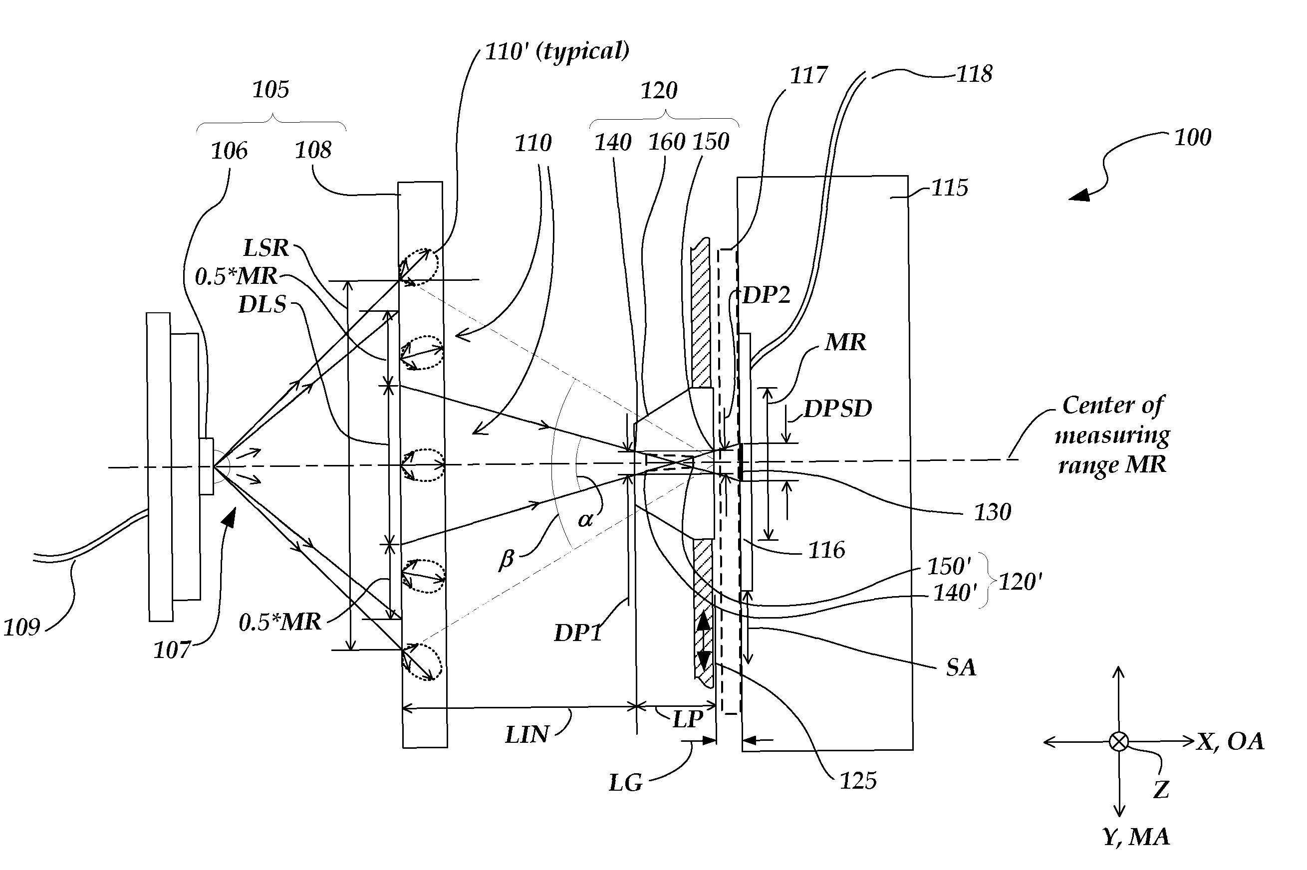
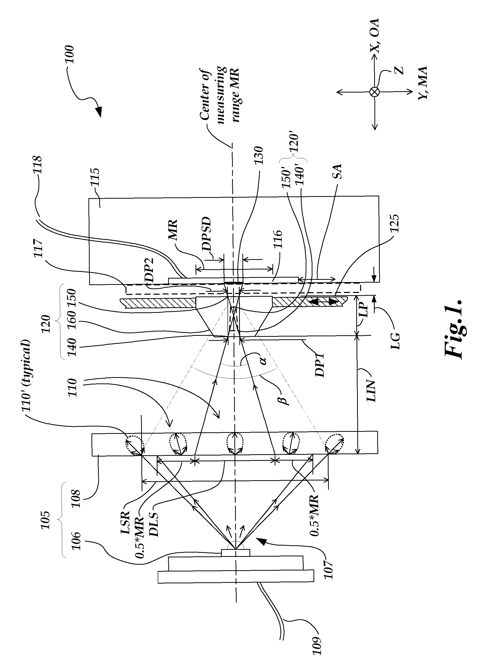
[0025]FIG. 1 is a diagram of a schematic cross-sectional view perpendicular to the measuring axis direction MA of a position sensing device 100 according to the present invention. FIG. 1 shows a measuring axis direction MA indicated as a Y axis direction, and an optical axis direction OA indicated as an X axis direction defined to be perpendicular to the Y-Z plane, which is defined to be parallel to the plane of the sensing surface 116. The position sensing device 100 comprises a diffuse light source 105, light source power line or lines 109, a position sensitive photodetector 115 comprising the sensing surface 116, signal line or lines 118, a protective window 117 (optional), and a moving aperture arrangement 120 located between the diffuse light source 105 and the position sensitive photodetector 115.

[0026]The position sensitive photodetector (or detector) 115 is fixed relative to the diffuse light source 105 and aligned with its sensing surface 116 opposing the diffuse light sour...

fourth embodiment

[0048]FIG. 6 is a diagram of a schematic cross-sectional view perpendicular to the measuring axis direction for a position sensing device 600 according to the invention. The 6XX series numbers in FIG. 6 that have the same “XX” suffix as 1XX and 2XX series numbers in FIGS. 1 and 2 may designate functionally similar or identical elements unless otherwise indicated. Thus, the operation of the position sensing device 600 may generally be understood by analogy with previous descriptions, and only certain aspects of its operation will be described here.

[0049]Regarding FIG. 6, the primary difference between the position sensing device 600 and the position sensing devices 100 and 200 of FIGS. 1 and 2 is that the diffuse light source 605 comprises a moving diffuser 608, attached to the moving aperture arrangement 620 by a diffuser holder 627. A fixed light generating portion (e.g., the LED 606) may generate light 607 that spans the dimension LSR along the measuring axis direction MA at a pla...


PUM


Abstract

A position sensing device comprises a light source that radiates diffuse source light along an optical axis direction to a detector, and a moving aperture arrangement positioned between the source and detector, to move perpendicular to the optical axis direction. The moving aperture arrangement comprises first and second limiting apertures, which angularly filter and transmit the diffuse source light to form a measurement spot on the detector. At least one signal output by the detector is indicative of a position of the movable member along a measurement axis. The angular intensity distribution of the angularly filtered rays of light which form the measurement spot is more consistent as a function of position along the measurement axis than the angular intensity distribution of the source light. The resulting consistent intensity distribution within the measurement spot throughout the measurement range enhances measurement linearity and accuracy.

Description

FIELD OF THE INVENTION[0001]The present invention relates to linear displacement sensors, and more particularly, to a linear displacement configuration that generates desirable measurement signals using a position sensitive photodetector.BACKGROUND OF THE INVENTION[0002]Various displacement sensors are known that provide signals which are indicative of a position using a linear variable differential transformer (LVDT). This type of system uses a primary solenoidal coil which generates an induced current in two secondary solenoidal coils, and the magnitude of the current in each secondary coil depends on the position of a ferromagnetic core that moves axially inside the coils. When the secondary coils are connected in reverse series, the position of the ferromagnetic core may be determined based on a resulting differential signal.[0003]In some applications, it is desirable to provide an optical displacement sensor which provides a linear displacement signal, in a manner analogous to ...

Claims


Application Information

Patent Timeline
Patent Type & Authority Patents(United States)
IPC IPC(8): G01B11/14
CPCG01D5/342
Inventor ALTENDORF, ERIC H.NAHUM, MICHAEL
Owner MITUTOYO CORP
Why Eureka
Try Eureka