
Method and apparatus for increasing the efficiency of low power amplifiers

a low-power amplifier and efficiency technology, applied in the direction of transmission, amplifiers with semiconductor devices only, amplifiers with semiconductor devices, etc., can solve the problems of high dc power consumption, large peak-to-average ratio of conventional rf amplifiers, and low efficiency, so as to reduce current consumption and increase the efficiency of an rf power amplifier.

Active Publication Date: 2011-03-01
QUALCOMM INC
View PDF10 Cites 12 Cited by
  • Summary
  • Abstract
  • Description
  • Claims
  • Application Information

AI Technical Summary

Problems solved by technology

Conventional RF amplifiers required to simultaneously amplify RF signals that have large peak-to-average ratios, are costly and relatively inefficient (i.e., consume much DC power).
However, during most of the time, the power output is only a small fraction of the power consumed from the Direct Current (DC) power supply, resulting in low efficiency.

Method used


Image

  • Method and apparatus for increasing the efficiency of low power amplifiers
  • Method and apparatus for increasing the efficiency of low power amplifiers
  • Method and apparatus for increasing the efficiency of low power amplifiers

Examples


Embodiment Construction

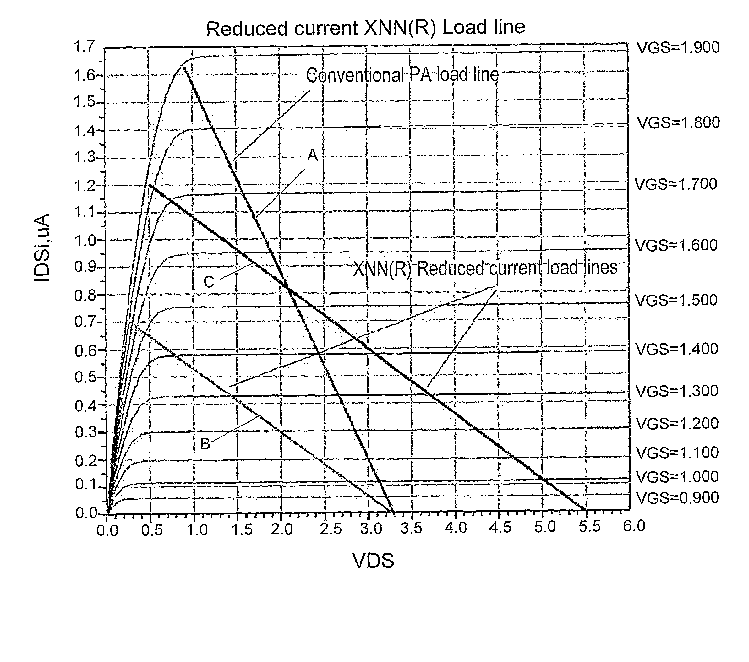
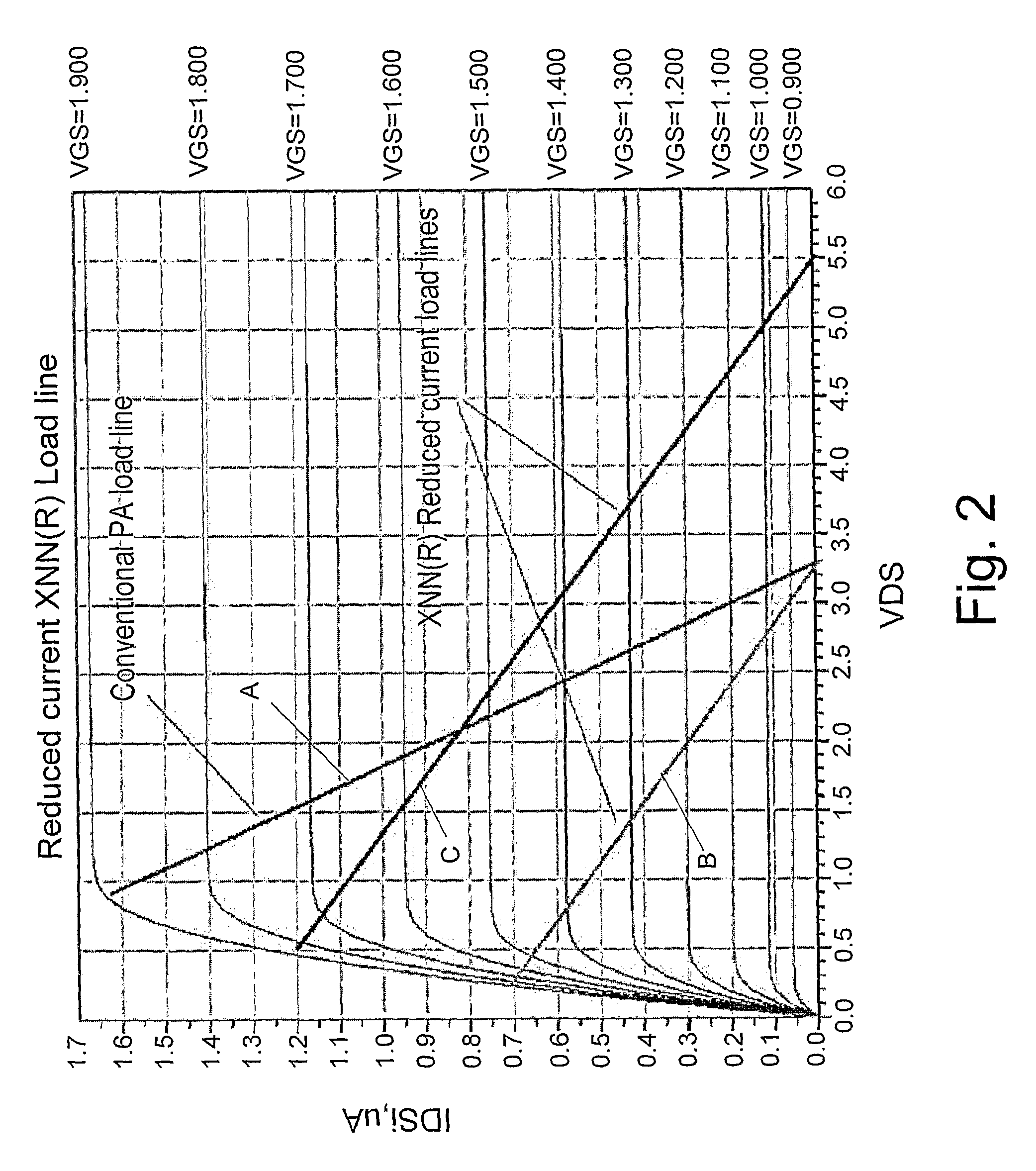
[0019]The present invention discloses a method and apparatus for applying XNN® technology for reducing the current consumption of a PA, without changing the DC power supply or the output power by retuning of the amplifier RF matching circuits. As a result, additional advantages are obtained: achieving higher power gain and lower heat dissipation on the main stage transistor of the PA. Such tuning or retuning may be done statically or dynamically, depending on power and efficiency requirements. Load tuning can be done for example, by adding or subtracting reactive components using RF switching, using variable-reactor diodes etc.

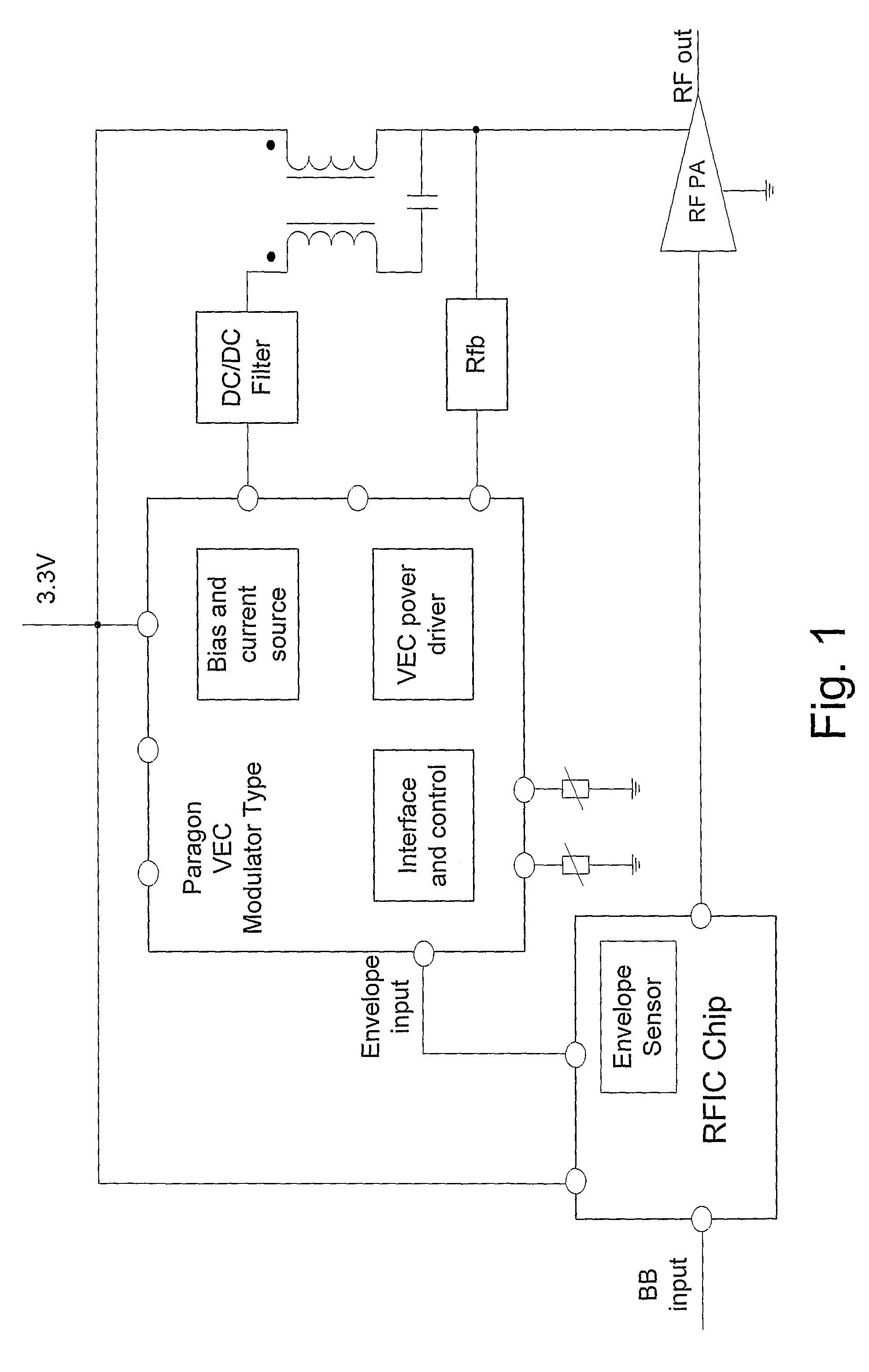
[0020]A typical implementation of an XNN® PA is illustrated in FIG. 1 (Prior Art). The Envelope Sensor (ES) provides high-level detection of the transmitted signals. A conventional technique for detection of RF signals employs diode-based detector. However, such detector diodes are usually capable of handling low power signals in the order of 1-10 mW. The VEC™...


PUM


Abstract

The present invention is directed to a method for reducing the current consumption and increasing the efficiency of an RF power amplifier (PA), while maintaining the output power. The desired output power of the PA is determined and for each level of the desired output power, the load that is connected to the output stage of the PA is tuned to essentially match the output impedance of the output stage to provide maximal gain. By doing so, the dynamic RF load line has a slope that causes it to intersect with the drain-source (or emitter-collector, in case of a bipolar transistor) voltage, across the output stage, at a value that corresponds to the voltage swing required to provide the desired output power.

Description

FIELD OF THE INVENTION[0001]The present invention relates to the field of high efficiency power amplifiers. More particularly, the invention relates to a matching technique for reducing current consumption of enhanced efficiency RF power amplifiers, without the need for changing its DC power supply and essentially without changing the output power.BACKGROUND OF THE INVENTION[0002]The technique of eXcess eNvelope enhancement (XNN®) for power amplifiers (PAs), particular for the low power WiFi and WiMAX market applications is disclosed in U.S. Pat. No. 6,437,641. This technique is a simplification of Envelope Tracking (ET), which is disclosed in US 2004 / 0018821.[0003]The Voltage Enhancement Circuit (VEC™), disclosed in U.S. Pat. No. 6,831,519, modulates the supply voltage of power amplifiers as part of the XNN® technique. Appropriate modulation of the supply voltage prevents saturation of the power amplifier, while amplifying signals that exceed a pre-defined programmable threshold.[0...

Claims


Application Information

Patent Timeline
Patent Type & Authority Patents(United States)
IPC IPC(8): H01Q11/12H04B1/04
CPCH03F1/02H03F1/0205H03F1/0227H03F1/56H03F1/565H03F2200/102H03F2200/387H03F1/0211
Inventor ELIA, AVNER
Owner QUALCOMM INC
Learn More