Failsafe system for material apparatus

a material reducing and failure-safe technology, applied in the field of failure-safe systems for material reducing apparatuses or machines, can solve the problems of metal, or some other hard material, prone to be intermixed with debris, affecting the service life so as to minimize the possibility of significant damage, facilitate servicing and/or replacement of such components, and maximize the throughput of the material reducing apparatus.

Active Publication Date: 2011-03-08
TEREX USA
View PDF22 Cites 11 Cited by
  • Summary
  • Abstract
  • Description
  • Claims
  • Application Information

AI Technical Summary

Benefits of technology

[0006]Another object of the present invention is to provide a failsafe system which when the system detects that the rotor initially strikes or contacts a hard material, such as metal, the failsafe system, substantially immediately upon detecting such contact, reverses the rotational direction of the top feed roller while also reducing the speed of the engine driving the rotor.
[0007]Yet another object of the present invention is to provide a failsafe system with a further safety feature which, when the failsafe system detects that a hard material, such as metal, is in the process of actually being reduced by the material reducing apparatus, facilitates an extremely rapid opening of a grate assembly so as to permit the rotation of the rotor to discharge the hard material on to the discharge conveyor before any shearing and / or damage can result to any of the internal components of the material reducing apparatus, e.g., the screen, the anvil(s), for example.
[0008]A further object of the present invention is to affix an accelerometer, to a bearing housing supporting the shaft which supports the rotor, such that the accelerometer detects generated vibrations when any of the supported hammers or strikers impacts against a hard material, such as metal, and the accelerometer generates an output signal which is immediately forwarded to main control system which, provided that the detected vibrations is sufficiently large, automatically reverses the rotational direction of the top feed roll to withdrawn the hard material or metal away from the arcing path of the rotor while, at the same time, slowing down the rotational speed of the rotor and also possibly actuating the grate assembly so as to sufficiently space the grate assembly away from the rotating rotor and prevent damage to the internal components of the material reducing apparatus.
[0010]A further object of the present invention is to provide a failsafe system which maximizes throughput of the material reducing apparatus while minimizes the possibility of any significant damage occurring to internal grinding / shearing components during operation.
[0011]Another object of the present invention is to mount the top feed roller to a pivotal clamshell assembly which facilitates improved access to the hammers or the strikers, the striker or hammer support blocks, the rotor the and the screen or grate, etc., to facilitate servicing and / or replacement of such components.

Problems solved by technology

A prevalent problem associated with prior art material reducing apparatus is that metal, or some other hard material, tends to be intermixed with the debris, logs, tree stumps, brush, yard waste, pallets or other material to be recycled.
If any hard material is attempted to be reduced by the material reducing apparatus, this normally causes the anvil(s), the hammer(s), the striker(s) and / or other internal components within the material reducing apparatus to be dented, chip, fracture and / or break.
The problem with such shear arrangements is that, although they are somewhat effective in minimizing damage to the material reducing apparatus, they still result in some damage occurring to the material reducing apparatus which, in turn, leads to costly down time while the material reducing apparatus is shut down so that the chipped, fractured or broken part(s) can be repaired or replaced.

Method used


Image

  • Failsafe system for material apparatus
  • Failsafe system for material apparatus
  • Failsafe system for material apparatus

Examples


Embodiment Construction

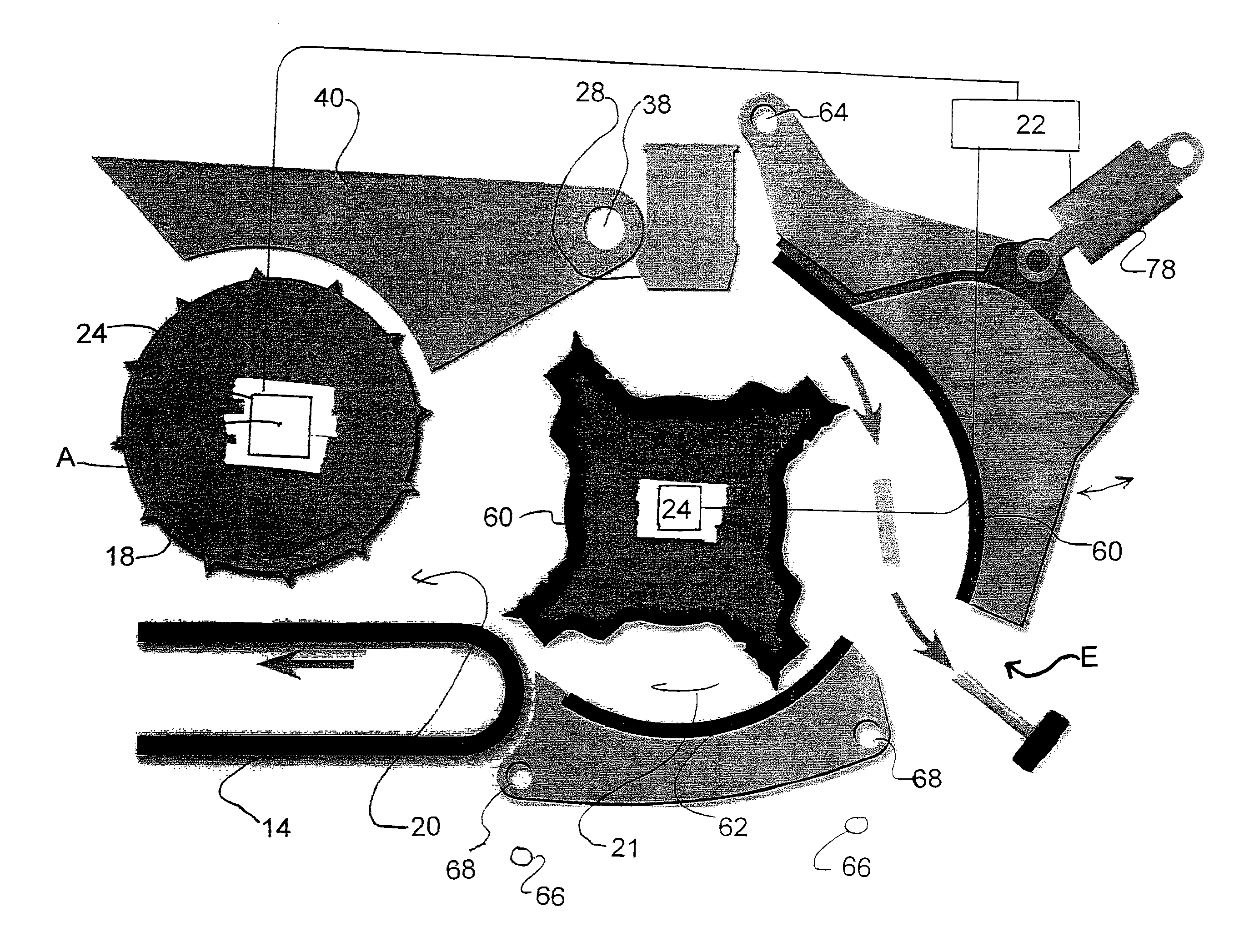
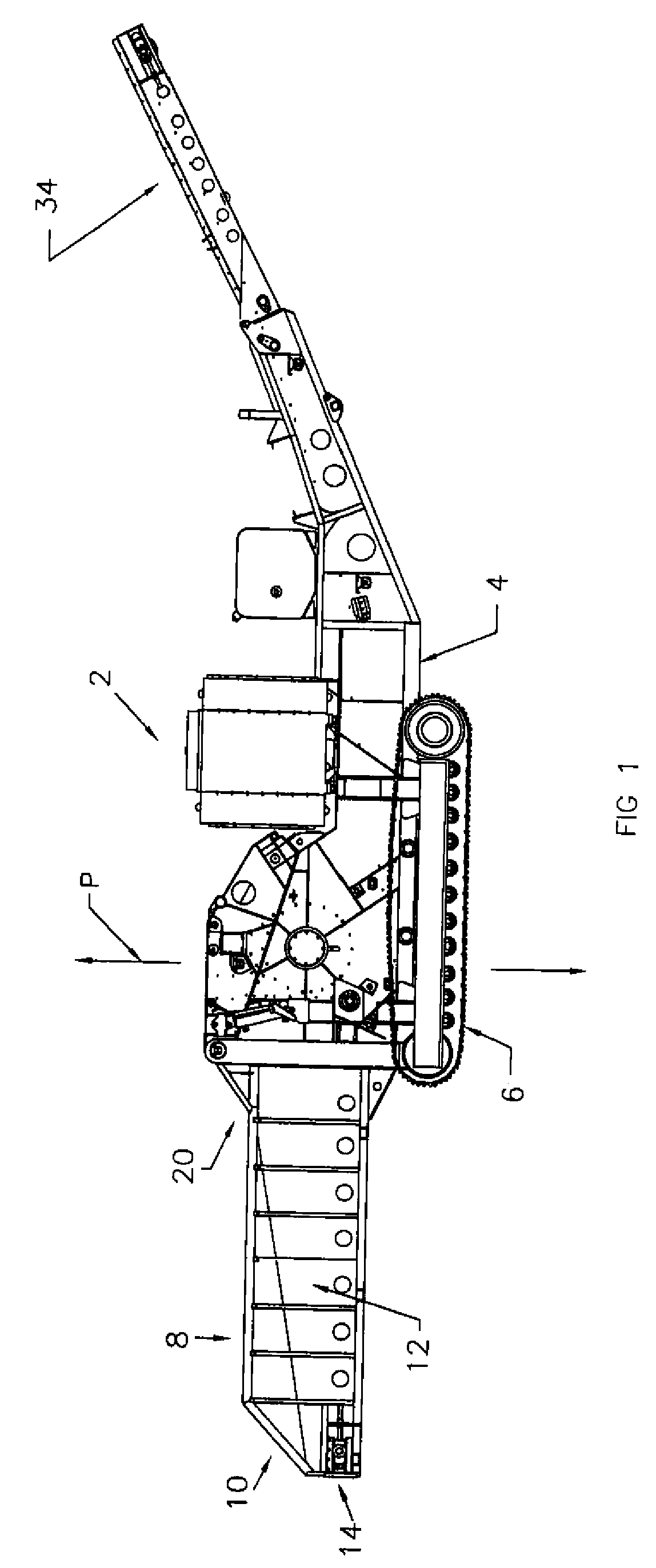
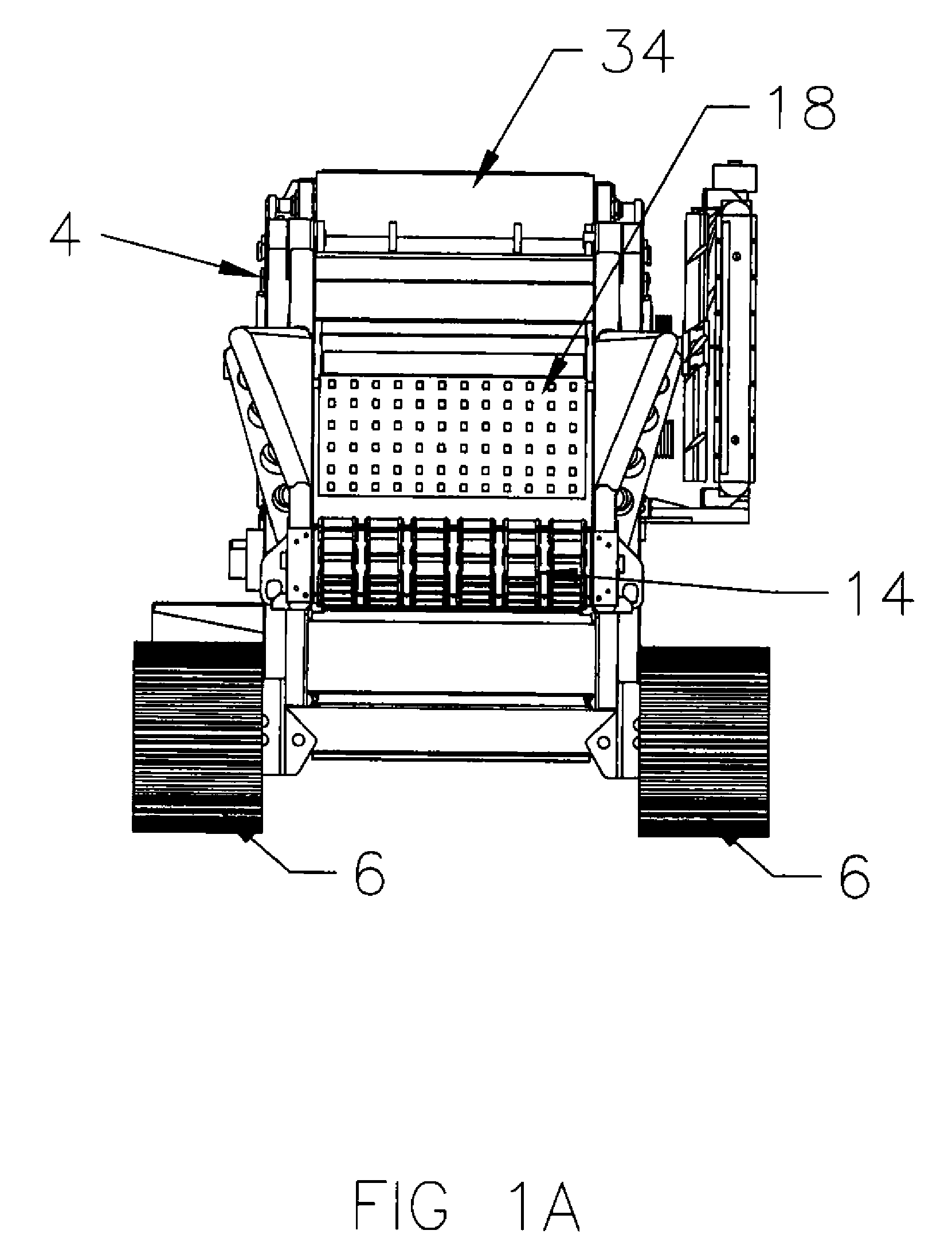
[0028]Turning now to FIGS. 1, 1A, 2 and 2A, a brief description concerning the various components of the present invention will now be briefly discussed. As can be seen in FIG. 1, a material reducing apparatus 2 is diagrammatically shown therein. The material reducing apparatus 2 is arranged to reduce materials such as debris, logs, tree stumps, tree limbs, brush, yard waste, pallets and the like into particles having a desired smaller particle size. According to this embodiment, the material reducing apparatus 2 includes a chassis or frame assembly 4 having a pair of tracks 6 which facilitate travel and maneuverability of the material reducing apparatus 2 to a desired location of a particular work site or onto a transportation trailer. It is conceivable that the chassis or frame assembly 4 may instead include a plurality of rotatable wheels and have a conventional hitch which facilitates connection to a conventional towing unit for towing the material reducing apparatus 2 to a desi...


PUM


Abstract

A material reducing apparatus comprising a feed conveyor, for conveying material to be reduced, and a feed roller cooperating with the feed conveyor. An upwardly rotatable rotor carrying a plurality of strikers which facilitate reduction of the material to be reduced and an anvil cooperating with the plurality of strikers to facilitate further reduction of the material to be reduced. A grate assembly, located adjacent an arcuate path of the rotor, which permits sufficiently reduced material to pass therethrough. The material reducing apparatus further includes a failsafe system which comprising an accelerometer supported by the rotor and coupled to a control system such that the accelerometer, upon detection of the rotor contacting a hard material, sends a signal to the control system. If the signal indicates a sufficiently large material, the control system reverses a rotational direction of the feed roller so that the feed roll rotates to withdraw the hard material from contact with the rotor. A section of the grate assembly may also be moved away from the rotor, by a release device, upon the release device receiving a command from the control system.

Description

FIELD OF THE INVENTION[0001]The present invention relates to a failsafe system for a material reducing apparatus or machine that essentially prevents damage from occurring to the material reducing apparatus or machine when the failsafe system detects an attempted reduction, e.g., a conversion of a large piece of material into smaller, more convenient pieces of material for subsequent handling and recycling purposes, of a “hard” material, such as tramp metal, by the material reducing apparatus or machine.BACKGROUND OF THE INVENTION[0002]A variety of different materials reducing machines and apparatuses are known in the art which receive large bulky materials, e.g., logs, tree stumps, brush, yard waste, pallets as well as other materials, and process the same for recycling or disposal, for example. Typically a large rotor, containing a plurality of replaceable blades, knives, teeth, hammers or strikers on a peripheral surface thereof, is rotated at relatively high speed so as to strik...

Claims


Application Information

Patent Timeline
Patent Type & Authority Patents(United States)
IPC IPC(8): B02C25/00
CPCB02C13/06B02C13/31B02C21/026
Inventor RAGNARSSON, ANDERS
Owner TEREX USA
Why Eureka
Try Eureka