Anti-roll bar for motor vehicles

a technology for motor vehicles and suspension systems, applied in the direction of springs/dampers, mechanical equipment, transportation and packaging, etc., can solve the problems of considerable strength of suspension systems, insufficient compactness of conventional systems, and considerable technical challenges to provide enhanced suspension systems. , to achieve the effect of compactness, compactness and improved suspension system for vehicles

Inactive Publication Date: 2011-03-08
VOLVO TRUCK CORP
View PDF20 Cites 9 Cited by
  • Summary
  • Abstract
  • Description
  • Claims
  • Application Information

AI Technical Summary

Benefits of technology

[0002]Contemporary road vehicles are provided with suspension systems functionally included between wheels and chassis thereof. These suspension systems are operable to accommodate and dampen vertical movement of the wheels when such vehicles are in motion, such movement arising in response to, for example, uneven road surfaces. Thus, the suspension systems are adapted to reduce a magnitude of mechanical shocks being transmitted via the suspension systems to the chassis. Moreover, such suspension systems are necessary to enhance comfort of persons travelling in the vehicles, and also to reduce damage to objects, for example goods, being transported in the vehicles. Furthermore, accommodation and dampening of vertical motion is especially important in commercial road vehicles, for example in trucks operable to transport relative large quantities of fragile goods. Commercial road vehicles are often heavy, for example weighing several tonnes, and are capable of transporting goods of comparable weight. Moreover, such weights require suspensions systems of considerable strength to provide efficient shock absorbing functionality, such strength requirements conventionally requiring the suspension systems to add to vehicle height and compromising designs of such vehicles.
[0005]The suspension system also includes connections between the vehicle axle and the trailing arm beams to reduce stress concentrations spatially where the trailing arm beams are connected to the vehicle axle. Such stresses are reduced by employing a special form of axle cradle which extends laterally beyond sides of each trailing arm beam. To further dissipate stresses, sponsons are attached to each trailing arm beam on opposite sides thereof to provide additional support to the axle cradle and thereby dissipate the stresses being transmitted in operation from the axle cradle over a greater expanse of the trailing arm beams.
[0009]It is desirable to provide an improved suspension system which is operable to address aforementioned limitations encountered with contemporary suspension systems, for example to enable suspension components to be included in such a manner so as to provide for more flexible design and a decrease in height build up of a vehicle.
[0011](c) a stabilizing arrangement coupled between the arm beam and the frame, the stabilizing arrangement being operable to at least partially resist a lateral rolling motion of said vehicle by way of torsional compliance exhibited by the stabilizing arrangement, said suspension system being configured so that said stabilizing arrangement is included between the proximate end of the one or more arm beams and their damper and spring assemblies for rendering the suspension system more compact.
[0012]The present invention is of advantage in that capable of providing a more compact and improved suspension system for vehicles.

Problems solved by technology

Moreover, such weights require suspensions systems of considerable strength to provide efficient shock absorbing functionality, such strength requirements conventionally requiring the suspension systems to add to vehicle height and compromising designs of such vehicles.
It is a considerable technical challenge to provide enhanced suspension systems in road vehicles in which severe height and compactness constraints are imposed of designers of such road vehicles.
For example, the conventional systems are often insufficiently compact which compromises vehicle design, for example regarding beneficial location of wheel axles so as to better dynamically bear loads of associated vehicles.
Moreover, the systems do not include their air springs located in most favourable positions.
Furthermore, the conventional systems do not provide desirably resilient roll characteristics which are important to optimize to prevent vehicles swaying can result in vehicles swaying when corning which can potentially affect vehicle dynamic handling characteristics.
Such constraints can potentially provide in operation non-optimal suspension characteristics.

Method used


Image

  • Anti-roll bar for motor vehicles
  • Anti-roll bar for motor vehicles
  • Anti-roll bar for motor vehicles

Examples


Embodiment Construction

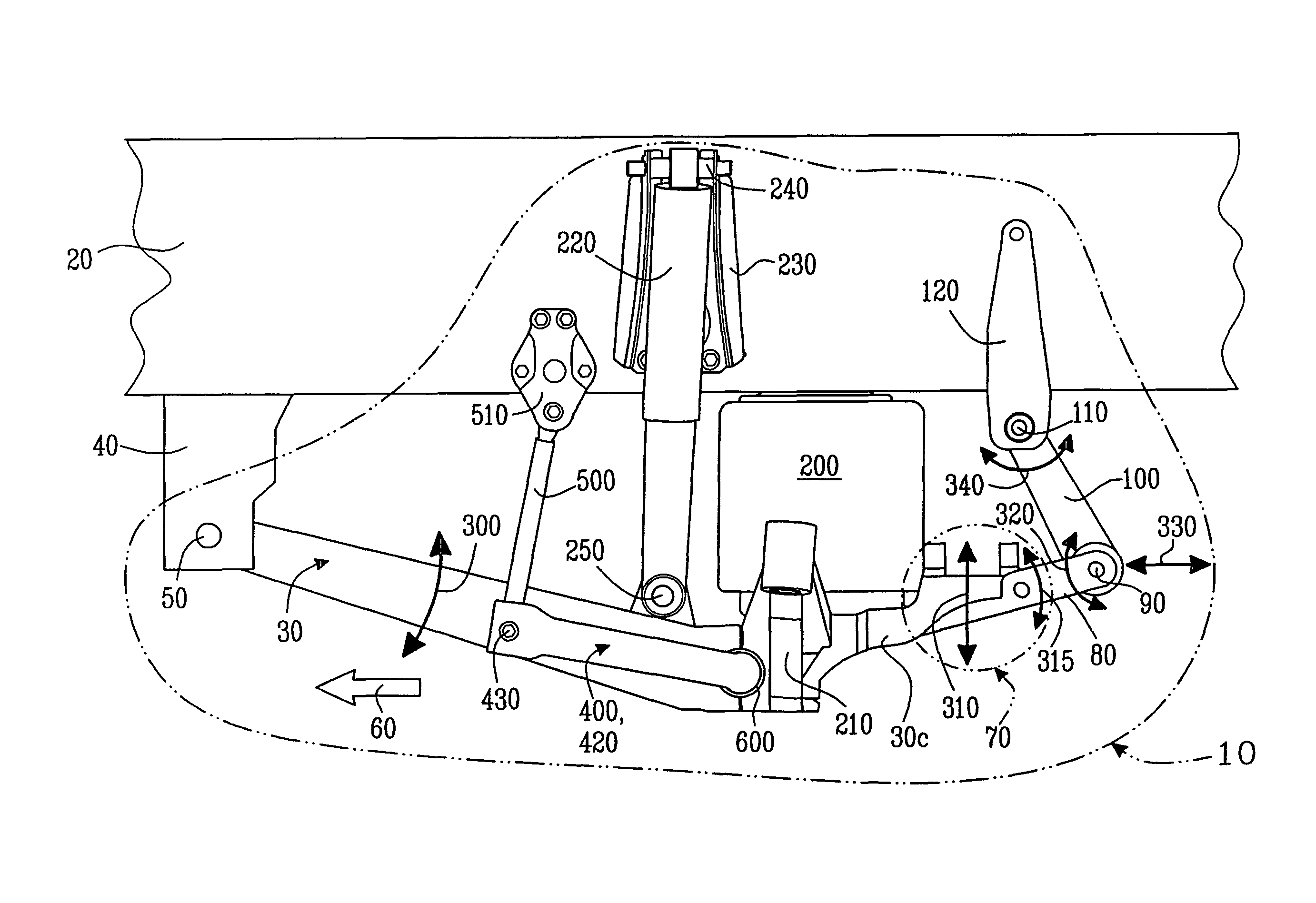
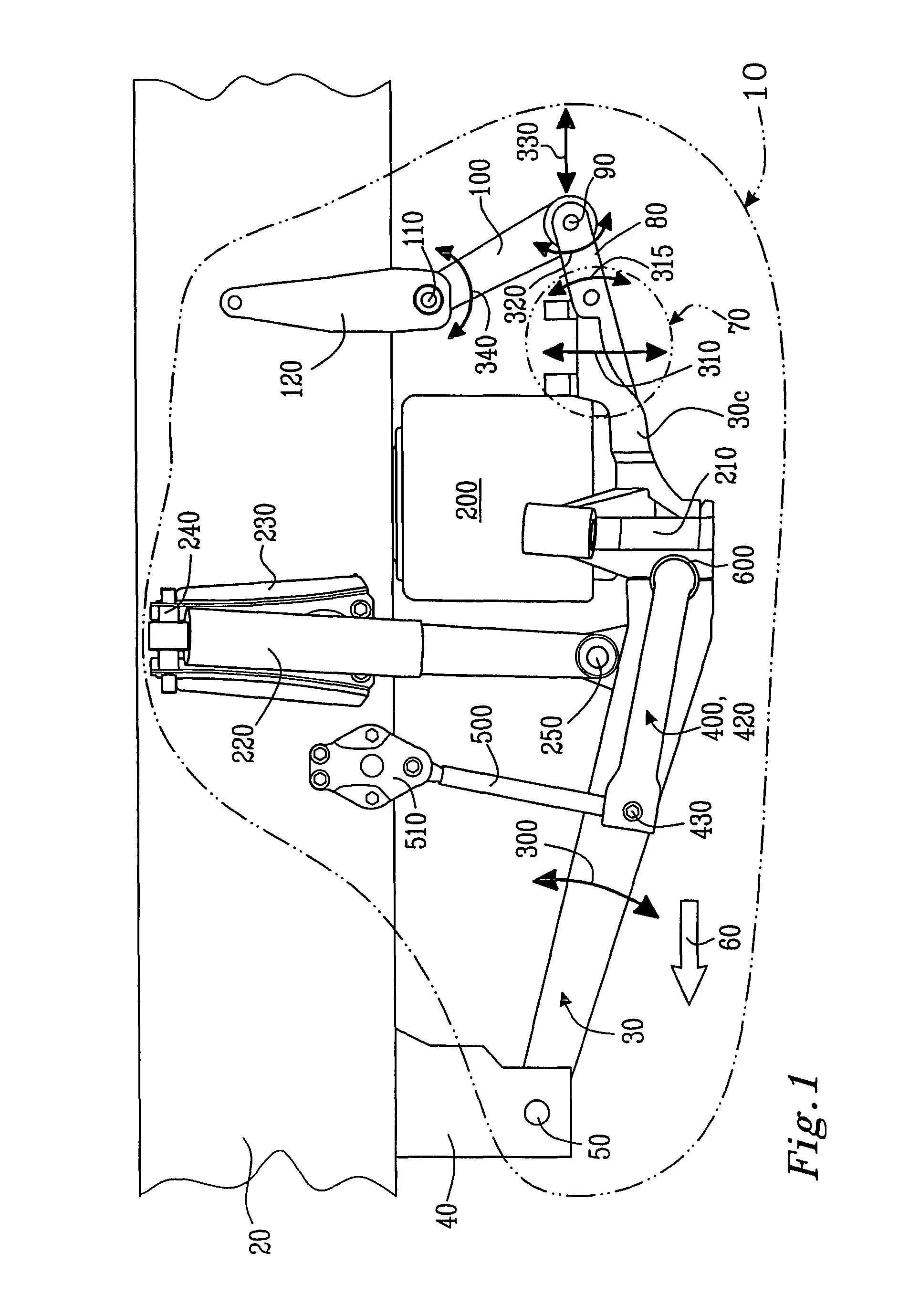
[0029]Referring to FIG. 1, there is shown a suspension system indicated generally by 10. The suspension system 10 is operable to provide a suspension function for a road vehicle (not shown), for example a heavy truck or similar goods vehicle. A portion of a chassis frame of the road vehicle is denoted by 20. The suspension system 10 includes a trailing arm beam 30 pivotally coupled at its proximate end via a pivot 50 to a frame bracket 40 mounted onto or integral with the frame 20. For reference, a normal forward direction of travel of the vehicle in operation is denoted by an arrow 60. The trailing arm beam 30 is included at both sides of the vehicle, namely the vehicle is provide with two such beams 30 on its left- and right-hand sides thereof.

[0030]The trailing arm beam 30 is elongate with its longitudinal axis substantially horizontal in operation, and optionally slightly inclined by circa 10 degrees relative to horizontal in operation as illustrated. Moreover, the trailing arm ...


PUM


Abstract

A suspension system for providing a suspension between wheels and a frame of a vehicle is provided. The system includes an arm beam pivotally mounted to the frame at its proximate end and coupled at its distal end to a guiding assembly enabling the arm beam to pivot in a vertical direction and to be restrained in lateral directions perpendicular to the vertical direction. The arm beam includes: (a) a spring and damper assembly near its distal end for providing a dampened resilient mount for the suspension; (b) a wheel axle beam coupled to the arm beam for bearing a load borne by the wheels transmitted directly in-line with a central axis of the spring and damper assembly; and (c) a stabilizer coupled between the arm beam and the frame, the stabilizer resisting a lateral rolling motion of the vehicle. The stabilizer is included between the proximate end of the arm beams and their damper and spring assemblies for rendering the system more compact.

Description

BACKGROUND AND SUMMARY[0001]The present invention relates to suspension systems for road vehicles, for example for air suspension systems adapted for heavy vehicles such as trucks and buses. Moreover, the invention also relates to methods of providing suspension for such road vehicles.[0002]Contemporary road vehicles are provided with suspension systems functionally included between wheels and chassis thereof. These suspension systems are operable to accommodate and dampen vertical movement of the wheels when such vehicles are in motion, such movement arising in response to, for example, uneven road surfaces. Thus, the suspension systems are adapted to reduce a magnitude of mechanical shocks being transmitted via the suspension systems to the chassis. Moreover, such suspension systems are necessary to enhance comfort of persons travelling in the vehicles, and also to reduce damage to objects, for example goods, being transported in the vehicles. Furthermore, accommodation and dampen...

Claims


Application Information

Patent Timeline
Patent Type & Authority Patents(United States)
IPC IPC(8): B60G21/055
CPCB60G9/003B60G21/0551B60G2204/421B60G2204/1222B60G2204/148B60G2200/31B60G9/006B60G21/055
Inventor LUNDMARK, ANDREAS
Owner VOLVO TRUCK CORP
Why Eureka
Try Eureka