Display device and optical device

a technology of optical devices and display devices, applied in the direction of optical elements, lighting and heating apparatuses, instruments, etc., can solve the problems of increased power consumption, difficult to distribute visible and invisible light uniformly over produced light efficiently falling on the light guide plate, etc., to achieve a higher degree of freedom

Inactive Publication Date: 2011-03-15
JAPAN DISPLAY WEST
View PDF9 Cites 9 Cited by
  • Summary
  • Abstract
  • Description
  • Claims
  • Application Information

AI Technical Summary

Benefits of technology

[0007]A possible solution to the above problem would be to arrange the visible and invisible light LEDs out of alignment with each other in the direction in proximity to but spaced from the side surface of the light guide plate. In this case, however, it is difficult to distribute visible and invisible light uniformly over the light guide plate due to various circumstances. For example, the invisible (or visible) light LEDs spaced from the side surface of the light guide plate cannot cause the produced light to efficiently fall upon the light guide plate. As a result, it is necessary to increase the number of LEDs so as to distribute invisible (or visible) light sufficiently over the light guide plate, thus resulting in increased power consumption.
[0009]It is an object of the present invention to provide a display device and optical device which can uniformly radiate light of different wavelengths while at the same time offering a higher degree of freedom in the arrangement of a plurality of light sources different in wavelength and number.
[0016]The present invention permits uniform radiation of light of different wavelengths while at the same time offering a higher degree of freedom in the arrangement of a plurality of light sources different in wavelength and number.

Problems solved by technology

However, it is difficult to arrange, in a limited space, namely, on the side surface of the light guide plate, a sufficient number of visible light LEDs in consideration of the display brightness required for visibility and a sufficient number of invisible light LEDs in consideration of the sensor sensitivity.
In this case, however, it is difficult to distribute visible and invisible light uniformly over the light guide plate due to various circumstances.
For example, the invisible (or visible) light LEDs spaced from the side surface of the light guide plate cannot cause the produced light to efficiently fall upon the light guide plate.
As a result, it is necessary to increase the number of LEDs so as to distribute invisible (or visible) light sufficiently over the light guide plate, thus resulting in increased power consumption.

Method used


Image

  • Display device and optical device
  • Display device and optical device
  • Display device and optical device

Examples


Embodiment Construction

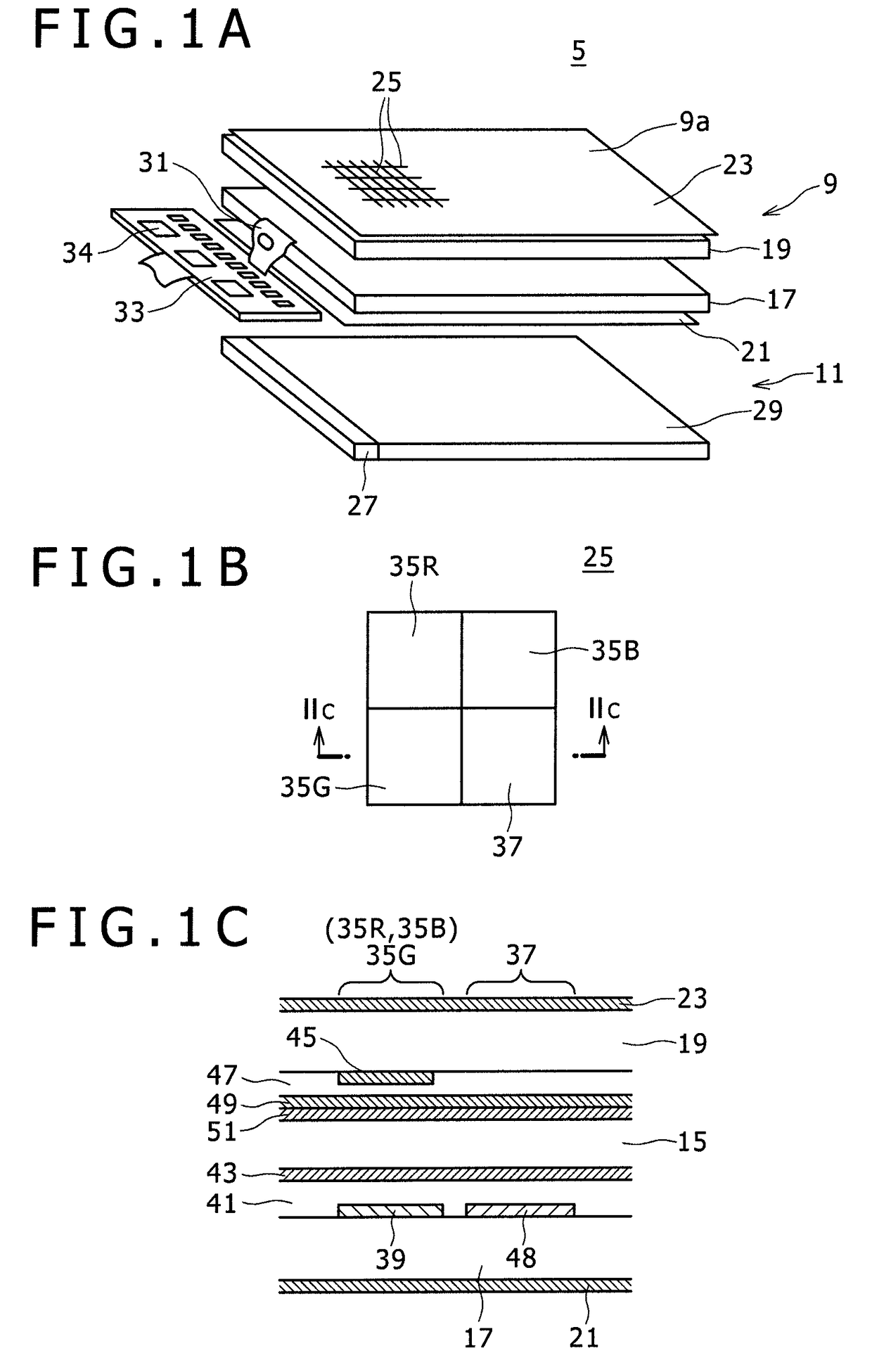
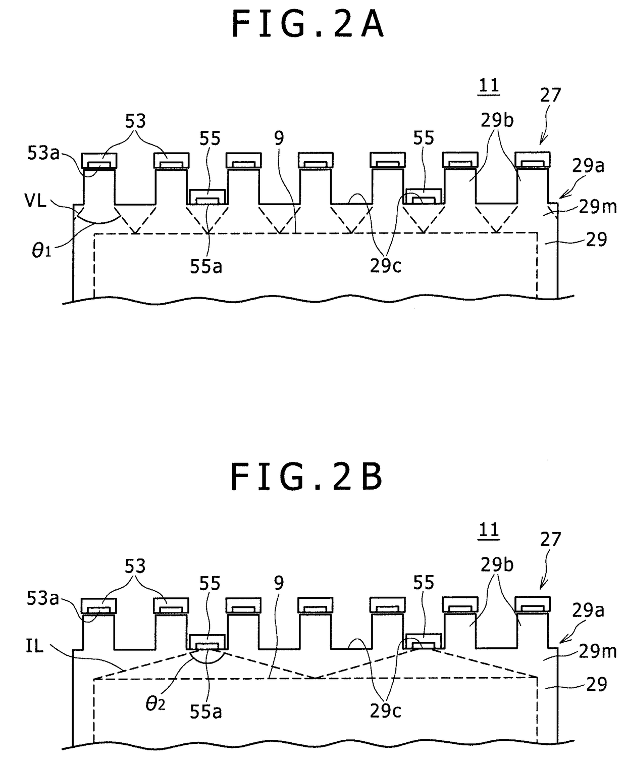
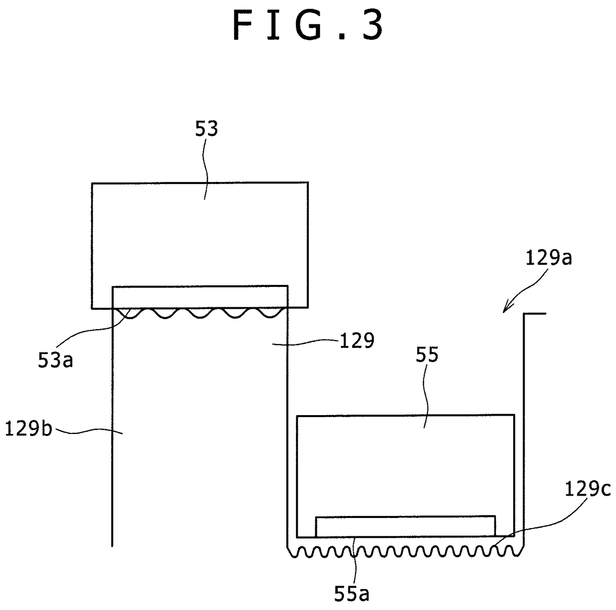
[0021]FIG. 1A is an exploded perspective view illustrating the schematic configuration of a display device 5 according to a first embodiment of the present invention. It should be noted that some members and components are omitted in FIGS. 1A to 1C.

[0022]The display device 5 is a so-called touch sensor display device. As a result, the display device 5 can not only display an image on a display surface 9a which is shown on the top side of the page, but also detect a detection target such as user's finger in contact with or proximity to the display surface 9a. It should be noted that the top side of FIGS. 1A to 1C may be referred to as the front side or front, and the bottom side thereof as the rear side, back or rear in the description given hereinafter.

[0023]A description will be given first of the configuration of the display device 5 for displaying an image.

[0024]The display device 5 includes, for example, a transmissive or semi-transmissive liquid crystal display device and has a...


PUM


Abstract

Disclosed herein is a display device including, a visual target, and a backlight adapted to illuminate the visual target from the rear, the backlight including, a plurality of first light sources, second light sources, and a light guide plate, wherein the light guide plate has a plurality of projecting portions on a side surface portion thereof upon which the light, produced by the plurality of first and second light sources is incident, the projecting portions being arranged, along the side surface portion and project toward the one side of the given direction, the plurality of first light sources are disposed to be opposed to the tip surfaces of the plurality of projecting portions, and the second light sources are disposed to be opposed to the bottom surfaces of recessed portions formed between the plurality of projecting portions.

Description

CROSS REFERENCES TO RELATED APPLICATIONS[0001]The present invention contains subject matter related to Japanese Patent Application JP 2007-305612 filed in the Japan Patent Office on Nov. 27, 2007, the entire contents of which being incorporated herein by reference.BACKGROUND OF THE INVENTION[0002]1. Field of the Invention[0003]The present invention relates to a display device having a backlight and an optical device applicable to the same and other devices.[0004]2. Description of the Related Art[0005]Display devices are known which have a backlight using two or more light sources in combination. For example, Japanese Patent Laid-Open No. 2005-275644 relates to a touch panel liquid crystal display device. In this display device, the backlight radiates visible and invisible light onto the display panel. The image is displayed with the visible light. The detection target (e.g., user's finger) in proximity to the display panel is detected by detecting, with sensors, the invisible light ...

Claims


Application Information

Patent Timeline
Patent Type & Authority Patents(United States)
IPC IPC(8): F21V7/04
CPCG02B6/0021G02B6/0073G02B6/0068G02F1/1335
Inventor YANG, YING BAOHIGUCHI, MASARUSUZUKI, HIROMASAKIMURA, SUSUMU
Owner JAPAN DISPLAY WEST
Why Eureka
Try Eureka