Magnetron

a technology of magnetron and air discharge conductance, which is applied in the manufacture of electrode systems, electric discharge tubes/lamps, spark plugs, etc., can solve the problems of poor vacuum, inability to provide a large air discharge conductance, and inability to discharge air in time, so as to reduce the maximum magnetic field strength, shorten the air exhaust time, and prevent the effect of poor vacuum

Active Publication Date: 2011-03-15
PANASONIC CORP
View PDF14 Cites 5 Cited by
  • Summary
  • Abstract
  • Description
  • Claims
  • Application Information

AI Technical Summary

Benefits of technology

[0010]The present invention is made in view of the above conventional circumstances. Thus, it is an object of the invention to provide a magnetron which can increase the air exhaust conductance without lowering the maximum magnetic field strength or causing the leakage of the higher harmonic waves.
[0015]According to the magnetron as set forth in the above item (1), since the input side pole piece has three or more penetration holes in the slanting portion thereof, a large air conductance can be provided, thereby being able to shorten the air exhaust time to discharge the air existing in the inside of the magnetron. Also, because the air of the inside of the magnetron can be discharged positively, the occurrence of a poor degree of vacuum within the magnetron can also be prevented. Further, since the area of each penetration hole is set for 16.6 mm2 or smaller, the lowering of the maximum magnetic field strength and the leakage of higher harmonic waves can be prevented.
[0016]According to the magnetron pole piece manufacturing method as set forth in the above item (2), since the penetration hole is formed in the axial direction (that is, in the vertical direction) over the large-diameter flat portion and slanting portion of the input side pole piece, the penetration hole can be formed simultaneously when the input side pole piece is manufactured by press working, which can minimize an increase in the cost for forming the penetration hole.
[0017]According to the magnetron pole piece manufacturing method as set forth in the above item (3), since three or more penetration holes are formed at given intervals in the peripheral direction of the slanting portion, a large air exhaust conductance can be secured when the magnetron is in operation, which makes it possible to shorten the air exhaust time to discharge the air existing in the inside of the magnetron. Also, because the air of the inside of the magnetron can be discharged positively, the occurrence of a poor degree of vacuum within the magnetron can also be prevented. Further, since the area of each penetration hole is set for 16.6 mm2 or smaller, the lowering of the maximum magnetic field strength and the leakage of higher harmonic waves can be prevented.
[0018]Also, in the case of a microwave using apparatus according to the invention, since it includes the above-mentioned magnetron, the air exhaust time can be shortened as well as the stable operation of the apparatus can be realized.

Problems solved by technology

This makes it impossible to provide a large air discharge conductance (an air exhaust efficiency), thereby taking much time to discharge the air.
Owing to the fact that it takes much time for the air exhaust, there is a fear that there can occur a poor degree of vacuum.
However, even when there is disposed a new opening in the input side pole piece 15 (there may also be the output side pole piece 14) in order to discharge the air on the input side with high efficiency, depending on the size of the opening, there is also a fear that the maximum magnetic field strength can be lowered or higher harmonic waves can leak.

Method used


Image

  • Magnetron
  • Magnetron
  • Magnetron

Examples


Embodiment Construction

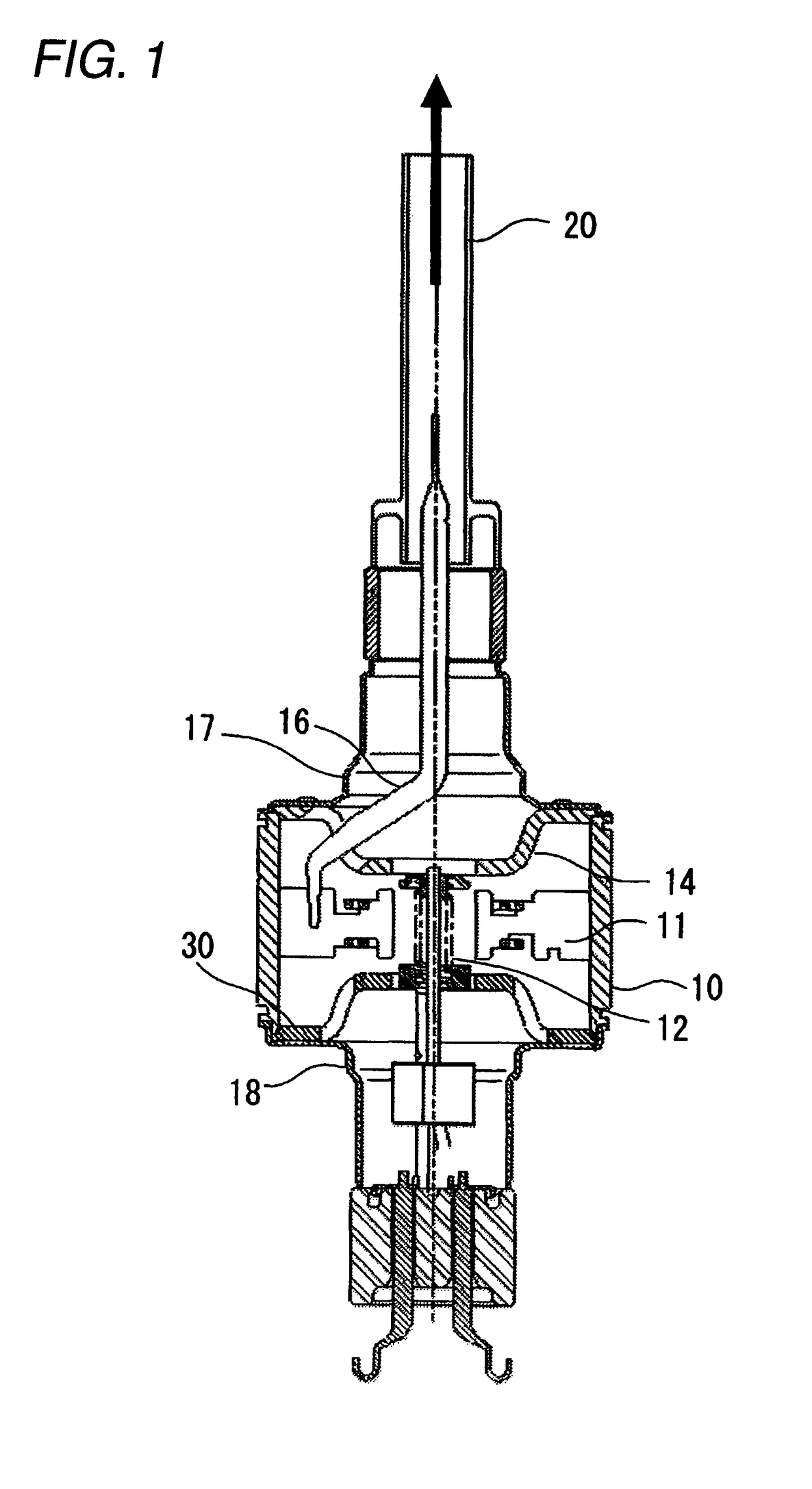
[0036]Now, description will be given below in detail of a preferred embodiment of a magnetron according to the invention with reference to the accompanying drawings.

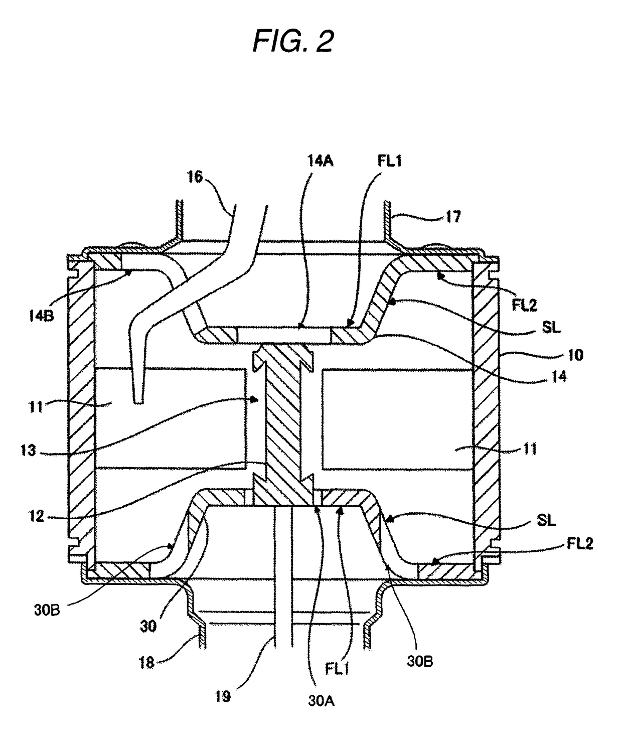
[0037]FIG. 1 is a longitudinal section view of a magnetron according to an embodiment of the invention, while FIG. 2 is an enlarged section view of the main portions of the magnetron shown in FIG. 1. In FIG. 2, the magnetron according to the present embodiment comprises: a cylindrical-shaped anode barrel member 10 having two openings respectively formed in two end portions thereof; a cathode structure member 12 disposed on the center axis of the anode barrel member 10; more than one anode vane 11 disposed radially through an action space 13 in the periphery of the cathode structure member 12 and fixedly mounted on the inner wall surface of the anode barrel member 10; and a pair of funnel-shaped pole pieces 14 and 30 respectively disposed in their associated ones of the two openings respectively formed in the two end port...


PUM


Abstract

The magnetron includes: a cylindrical-shaped anode barrel member 10 having two openings respectively formed in the two end portions thereof; a cathode structure member 12 disposed on the center axis of the anode barrel member 10; more than one anode vane 11 disposed radially through an action space 13 in the periphery of the cathode structure member 12 and fixedly mounted on the inner wall surface of the anode barrel member 10; and, a pair of funnel-shaped pole pieces 14 and 30 respectively disposed in their associated ones of the two openings formed in the two end portions of the anode barrel member 10, each pole piece including a small-diameter flat portion FL1 having a penetration hole formed in the central portion thereof, a large-diameter flat portion FL2 having a diameter larger than the diameter of the small-diameter flat portion FL1, and a conical-shaped slanting portion SL for connecting the large-diameter flat portion FL2 and small-diameter flat portion FL1 to each other. Of the pair of pole pieces 14 and 30, the input side pole piece 30 includes, besides the penetration hole 30A formed in the central portion thereof, three or more, preferably, four penetration holes 30B respectively formed in the slanting portion SL thereof, each hole having an area of 16.6 mm2.

Description

BACKGROUND OF THE INVENTION[0001]1. Field of the Invention[0002]The present invention relates to a magnetron for used in equipment using microwaves such as a microwave oven.[0003]2. Description of the Related Art[0004]FIG. 15 is a longitudinal section view of a general magnetron which is conventionally used in a microwave oven, and FIG. 16 is an enlarged section view of the main portions of the magnetron shown in FIG. 15. In FIGS. 15 and 16, in the inside of a cylindrical-shaped anode barrel member 10, there are radially disposed anode vanes 11, while spaces respectively enclosed by the mutually adjoining anode vanes 11 and anode barrel member 10 constitute a cavity resonator. In the central portion of the anode barrel member 10, there is disposed a cathode structure member 12, while a space enclosed by the anode structure member 12 and anode vane 11 constitutes an action space 13. On the upper end of the anode barrel member 10, there is fixedly mounted a pole piece (which is herein...

Claims


Application Information

Patent Timeline
Patent Type & Authority Patents(United States)
IPC IPC(8): H01J25/50
CPCH01J9/385H01J23/10H01J25/50
Inventor ISHII, TAKESHIKUWAHARA, NAGISAAIGA, MASAYUKI
Owner PANASONIC CORP
Why Eureka
Try Eureka