
Programmable logic device having an embedded test logic with secure access control

a technology of access control and programmable logic, applied in the direction of unauthorized memory use protection, instruments, pulse techniques, etc., can solve the problems of invalidating verification and validation, unable to learn the user's design,

Inactive Publication Date: 2011-03-15
INTUITIVE RES TECH
View PDF15 Cites 8 Cited by
  • Summary
  • Abstract
  • Description
  • Claims
  • Application Information

AI Technical Summary

Problems solved by technology

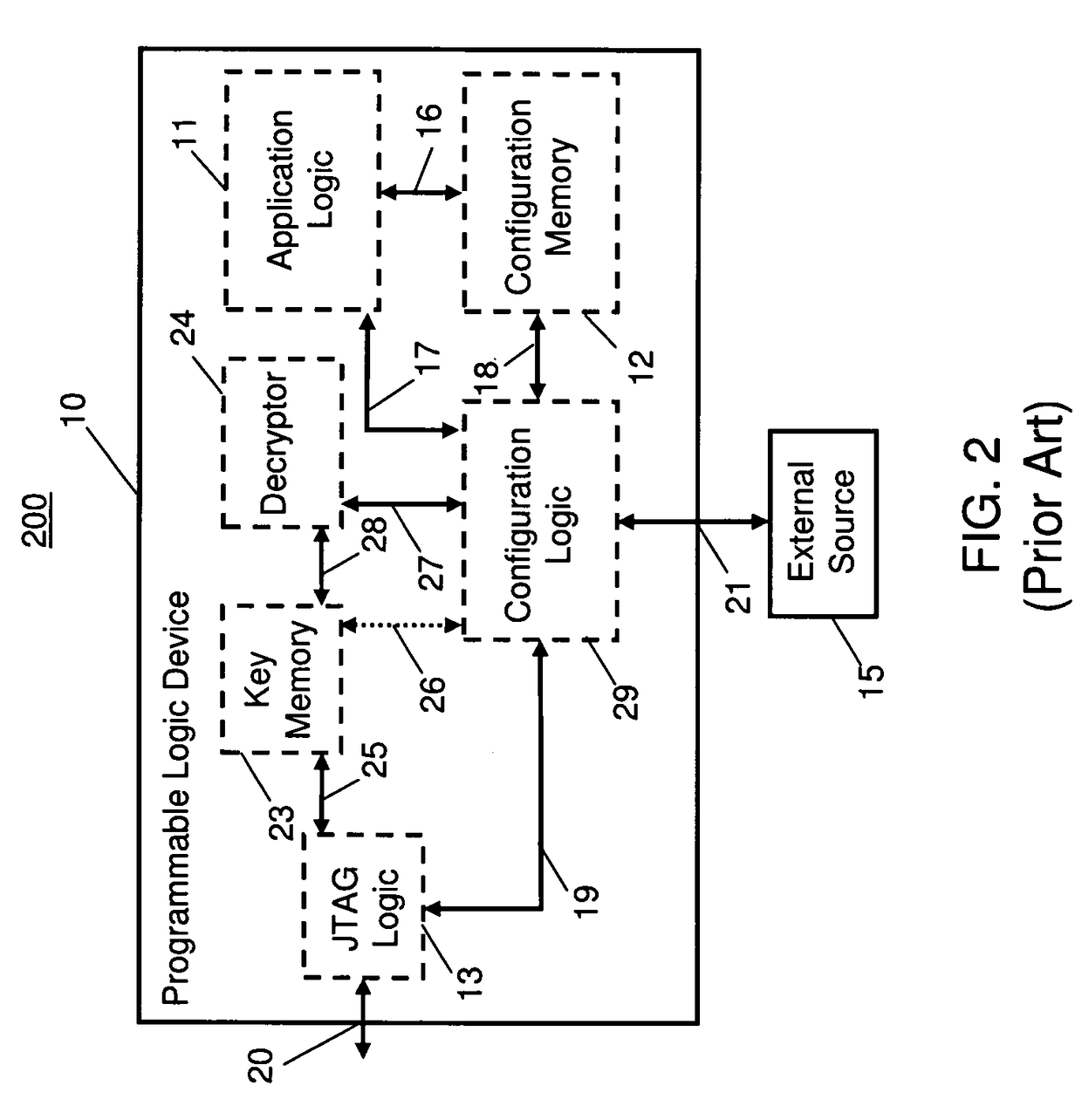
When the PLD configuration of FIG. 2 is being loaded with encrypted data, an attacker who monitors the bitstream as it is being loaded receives only the encrypted bitstream and cannot learn the user's design by this method.
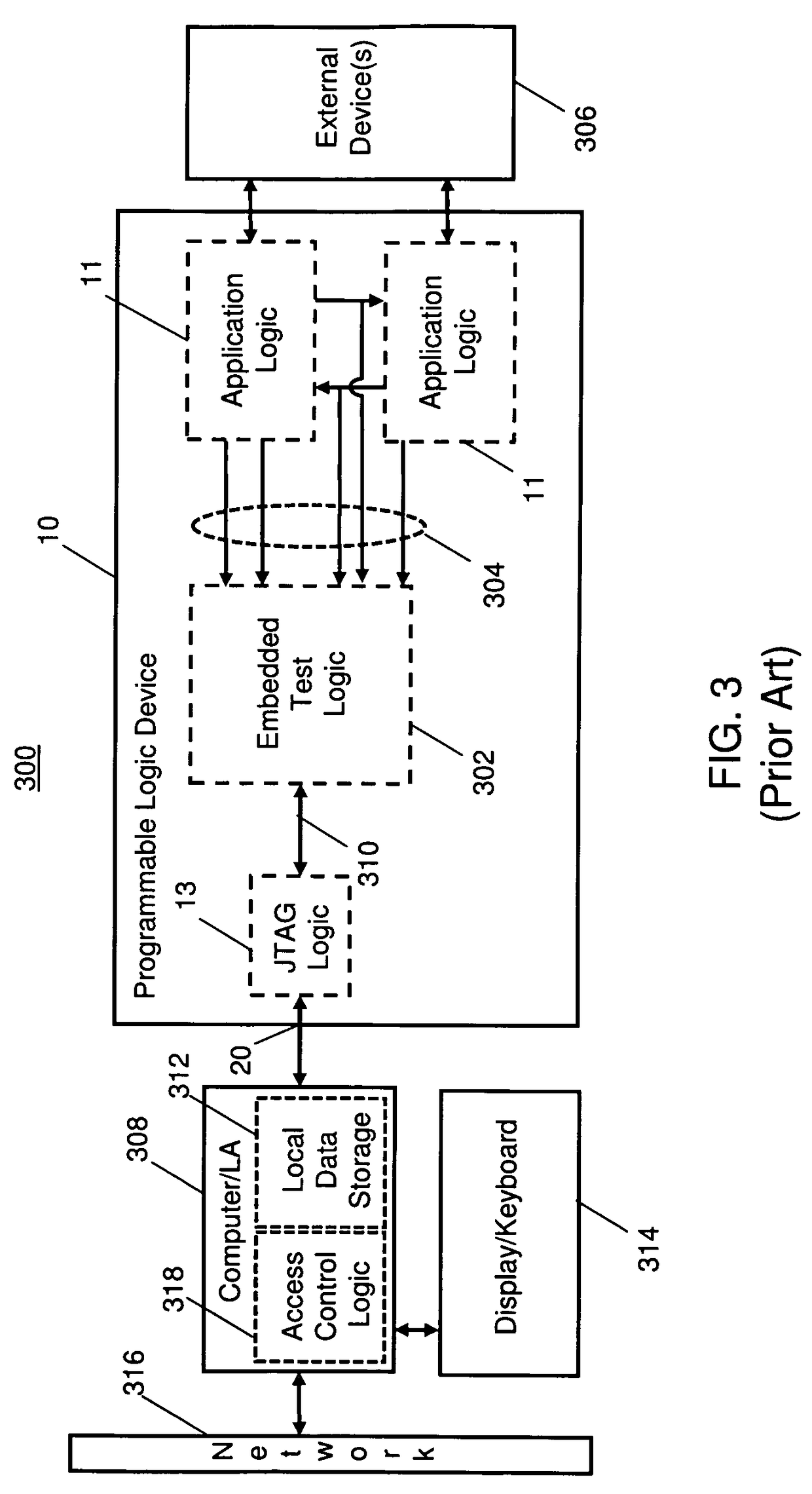
The removal of the embedded test logic 302, however, changes the PLD's circuit level design, thereby invalidating verification and validation results from the testing of the PLD 10.

Method used


Image

  • Programmable logic device having an embedded test logic with secure access control
  • Programmable logic device having an embedded test logic with secure access control
  • Programmable logic device having an embedded test logic with secure access control

Examples


first embodiment

[0049]FIG. 5 depicts an exemplary PLD configuration 500 in accordance with a PLD configuration of the present invention. An access control logic 502 created on a PLD 10 controls access to embedded test logic 302. The access control logic 502 interfaces with JTAG logic 13 via a bus 504. Under one arrangement, an external device, such as a tester, logic analyzer, waveform / signal analyzer, etc., can interface with the embedded test logic 302 through the access control logic 502. The JTAG logic 13 comprises an interface port 20 for communication of data between the external analyzer and the embedded test logic 302. The access control logic 502 interfaces with the embedded test logic 302 via a bus 310. According to the invention, the JTAG logic 13 cannot access the output of the embedded test logic 302 unless an access control requirement of the access control logic 502 is met, for example a hash operation on a user supplied data matching an internally stored access code (or key) 506. Th...

second embodiment

[0050]FIG. 6 depicts an exemplary PLD configuration 600 in accordance with a PLD configuration of the present invention. Referring to FIG. 6, access control and decryption logic 602 is placed between the JTAG logic 13 and the embedded test logic 302. As with the exemplary PLD configuration 500 of FIG. 5, a user of the JTAG port 20 cannot access the output 310 of the embedded test logic 302 without meeting access control requirements enforced by the access control and decryption logic 602. Additionally, access control and decryption logic 602 is able to decrypt information it receives from an external port, for example a configuration access port 21 via configuration logic 29 and bus 27 (note that other components used for programming the PLD 10 shown in FIGS. 1 and 2 are present but not depicted). Alternatively, access control and decryption logic 602 may decrypt data received from a computer / logic analyzer 308 via another input / output (I / O) port 604. I / O port 604 might alternativel...


PUM


Abstract

An improved configuration for a programmable logic device and an improved method for configuration of a programmable logic device are provided. A programmable logic device such as field programmable logic device is configured to include an application logic, an embedded test logic that monitors the application logic, and an access control logic that grants access to an external device to embedded test data provided that an access control requirement is met that is based upon a key stored in a memory and information received from the external device.

Description

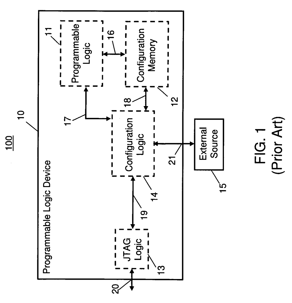
GOVERNMENT RIGHTS[0001]This invention was made with Government support under W31P4Q-05-A-0031 awarded by US Army Aviation and Missile Command. The Government has certain rights in the invention.FIELD OF THE INVENTION[0002]This invention generally relates to the field of programmable logic devices and more particularly to the protection of embedded test data after configuration of such devices.BACKGROUND OF THE INVENTION[0003]A programmable logic device (PLD) is an electronic component used to build configurable digital circuits. Unlike a logic gate, which has a fixed function, a PLD has an undefined function at the time of manufacture. Before the PLD can be used in a circuit it must be programmed (i.e., configured). One variant of a PLD is a field programmable gate array (FPGA), which uses a grid of logic gates. The programming or configuration of the FPGA is done by a user, not by the manufacturer.[0004]FIG. 1 shows a prior art configuration 100 for a programmable logic device (PLD...

Claims


Application Information

Patent Timeline
Patent Type & Authority Patents(United States)
IPC IPC(8): H03K19/00H03K19/173G06F11/30G06F12/14
CPCG01R31/318516H03K19/17764H03K19/17768
Inventor FULKS, III, CHARLES E.
Owner INTUITIVE RES TECH
Learn More