Phase lock loop with a multiphase oscillator

a multi-phase oscillator and phase lock technology, applied in the direction of electrical equipment, automatic control, etc., can solve the problems of insufficient phase resolution, sensitive delay of inverters, and insufficient prior art phase determination techniques, etc., to achieve finer phase resolution, increase phase resolution, and high ring oscillation frequency

Inactive Publication Date: 2011-03-15
III HLDG 12 LLC
View PDF8 Cites 19 Cited by
  • Summary
  • Abstract
  • Description
  • Claims
  • Application Information

AI Technical Summary

Benefits of technology

[0006]The phase lock loop of the present invention includes a multiphase oscillator such as a rotary traveling wave oscillator having a plurality of digital inputs, but instead of one DQ flip-flop, a plurality of DQ flip-flops is used to clock the digital inputs. The plurality of DQ flip-flops are offset in time from each other and drive the oscillator to generate a plurality of multiphase signals. The plurality of DQ flip-flops activate the plurality of digital inputs in the oscillator at zero crossing points of the traveling wave thereby eliminating perturbations in the phase signals from the oscillator. A DQ flip-flop connected to the oscillator determines direction of travel (clockwise or counterclockwise) of the traveling wave. A look-up table, addressed by multiphase signals from the oscillator and the direction of the traveling wave, determines the current fractional phase of the oscillator. The oscillator allows for higher ring oscillation frequencies, thereby considerably increasing phase resolution. The increased phase resolution is converted to digital form in the feedback path of the phase lock loop, permitting a much finer phase resolution than heretofore possible while at the same time reducing phase quantization noise. In a feed-forward path, frequency dividers divide an output signal of the oscillator to a desired frequency increasing phase resolution in the transmitted signal.

Problems solved by technology

Prior art techniques for phase determination in a phase lock loop are often difficult, resource intensive, and not accurate enough.
The delay of inverters are sensitive to process and temperature variations and is limited to a time resolution of 20 ps based on the state of the technology.
Since the phase resolution is dependent on the timing resolution, the phase resolution is also limited.

Method used


Image

  • Phase lock loop with a multiphase oscillator
  • Phase lock loop with a multiphase oscillator
  • Phase lock loop with a multiphase oscillator

Examples


Embodiment Construction

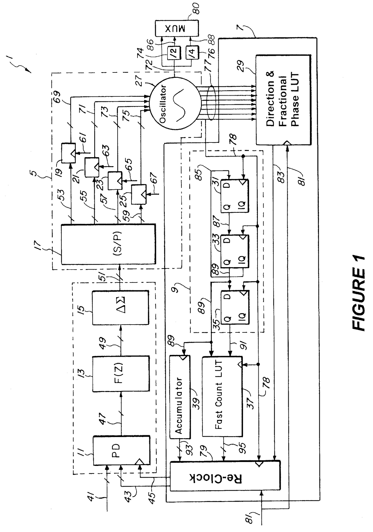
[0025]FIG. 1, shows a phase lock loop according to the present invention. A phase detector 11 receives a reference phase signal 41, a total phase signal 43, and a clock signal 45. The reference phase signal 41 represents a carrier frequency to lock to. The phase detector 11 compares the reference phase signal 41 to the total phase signal 43 upon receipt of the clock signal 45 and generates a control signal 47 which is proportional to the phase difference between the reference phase signal 41 and the total phase signal 43. Ideally the phase difference or error signal is zero.

[0026]A filter 13 receives the control signal 47 from the phase detector 11 and averages the control signal 47, generating a filtered control signal 49. A ΔΣ modulator 15 receives the filtered control signal 49 and performs a noise shaping function on the filtered control signal 49. The ΔΣ modulator 15 oversamples the filtered control signal 49 to push any noise within the filtered control signal 49 into a higher...


PUM


Abstract

A phase lock loop utilizes a multiphase oscillator having a plurality of digital inputs. A plurality of DQ flip-flops, offset in time from each other generate a plurality of control signals to remove control phase information from the oscillator in digital form. A DQ flip-flop connected between any two digital inputs on the oscillator determines direction of the traveling wave. The direction and phase information address a look-up table to determine the current fractional phase of the oscillator. A divide by N circuit is used to reduce the oscillator frequency. A total phase indicator signal for the oscillator is determined using the current fractional phase. The total phase is compared to a reference phase to produce a control signal for making adjustments to the oscillator. In a feed-forward path, frequency dividers divide a high frequency signal from the oscillator to a lower desired frequency, thereby increasing phase resolution.

Description

BACKGROUND OF THE INVENTION[0001]1. Field of the Invention[0002]The present invention relates to phase lock loops, and specifically to phase lock loops using multiphase oscillators.[0003]2. Description of Related Art[0004]Prior art techniques for phase determination in a phase lock loop are often difficult, resource intensive, and not accurate enough. One such prior art system, disclosed in Staszewski et al. (U.S. Pat. No. 6,326,851), determines a digital fractional phase by passing a clock signal from a 2.4 GHz voltage controlled oscillator through a chain of inverters. Each inverter produces a clock pulse slightly delayed from the immediately previous inverter. The resulting staggered clock phases are then sampled by a reference clock. The delay of inverters are sensitive to process and temperature variations and is limited to a time resolution of 20 ps based on the state of the technology. Since the phase resolution is dependent on the timing resolution, the phase resolution is a...

Claims


Application Information

Patent Timeline
Patent Type & Authority Patents(United States)
IPC IPC(8): H03L7/099
CPCH03L7/0995H03L7/183H03L7/1806H03L2207/50H03B5/1852
Inventor LIANG, PAUL CHENG-POTAKINAMI, KOJI
Owner III HLDG 12 LLC
Why Eureka
Try Eureka