Actuator drive control device

a technology of drive control and actuator, which is applied in the direction of dynamo-electric converter control, motor/generator/converter stopper, shock absorber, etc., can solve the problem of difficult to accurately vibrate the movable member of the actuator in a sine wave shape, and achieve the effect of reducing the burden on the controller, good accuracy and effective vibration-damping for

Inactive Publication Date: 2011-03-29
HONDA MOTOR CO LTD
View PDF23 Cites 1 Cited by
  • Summary
  • Abstract
  • Description
  • Claims
  • Application Information

AI Technical Summary

Benefits of technology

[0008]In order to achieve the above-mentioned object, according to a first feature of the invention, there is provided an actuator drive control device comprising: a controller; and an actuator; the controller supplying a target electric current to the actuator to periodically drive the actuator in an expanding and contracting manner with a target vibration waveform; and the controller setting the target electric current by synthesizing a driving primary electric current waveform corresponding to the target vibration waveform for the actuator, with a higher-order electric current waveform which eliminates a higher-order vibration component of the actuator depending on the driving primary electric current waveform.
[0012]With the arrangement of the first feature, the controller supplies a target electric current to the actuator to periodically drive the actuator in an expanding and contracting manner with a target vibration waveform; and synthesizes a driving primary electric current waveform corresponding to the target vibration waveform for the actuator, with a higher-order electric current waveform which eliminates a higher-order vibration component of the actuator depending on the driving primary electric current waveform, thereby setting a target electric current. Therefore, it is possible to cancel the higher-order vibration component(s) superimposed on the target vibration waveform for the actuator, thereby driving the actuator with the target vibration waveform with a good accuracy.
[0013]With the arrangement of the second feature, the higher-order electric current waveforms synthesized with the driving primary electric current waveform includes at least one of the driving secondary electric current waveform and the driving tertiary electric current waveform. Therefore, it is possible to alleviate the burden of the controller by ignoring the quaternary and still higher-order vibration components which are difficult to handle because of a high frequency and which only slightly affect the target vibration waveform for the actuator, while reliably canceling the secondary and tertiary vibration components which greatly affect the target vibration waveform for the actuator.
[0014]With the arrangement of the third feature, the actuator operates the active vibration isolation support system with the target vibration waveform depending on the vibration state of the vibrator. Therefore, it is possible to exhibit an effective vibration-damping force by the active vibration isolation support system, thereby effectively blocking transmission of the vibrations of the vibrator.

Problems solved by technology

In the case where an actuator using a solenoid is periodically driven in an expanding and contracting manner, an electric current waveform of a sine wave shape input to the actuator and a vibration waveform of the movable member of the actuator establish a nonlinear relationship therebetween, and a primary vibration waveform of a sine wave shape for the movable member is overlapped by higher-order vibration waveforms such as a secondary vibration waveform having a twofold frequency and a tertiary vibration waveform having a threefold frequency, so that it is disadvantageously difficult to vibrate the movable member of the actuator in an accurate sine wave shape.

Method used


Image

  • Actuator drive control device
  • Actuator drive control device
  • Actuator drive control device

Examples


Embodiment Construction

[0020]The present invention will now be described by way of an embodiment with reference to the accompanying drawings.

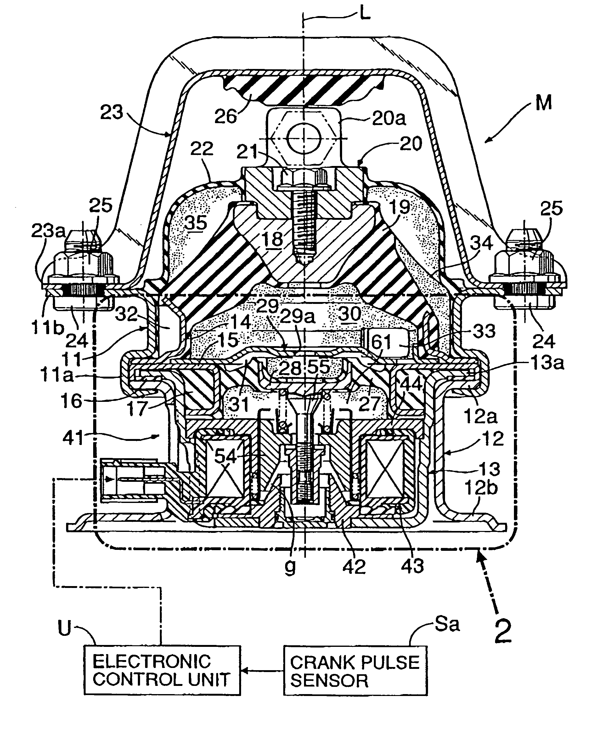
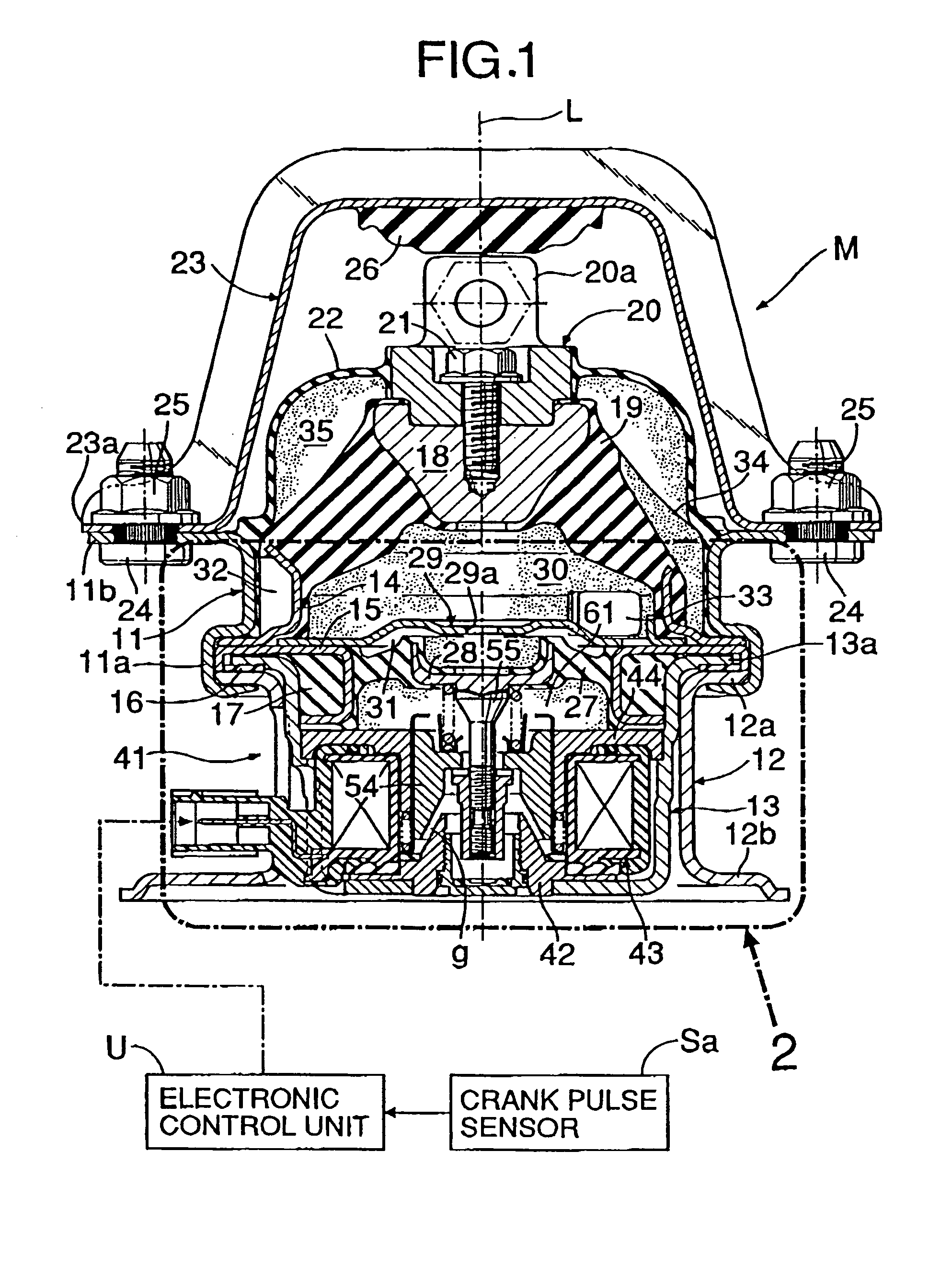
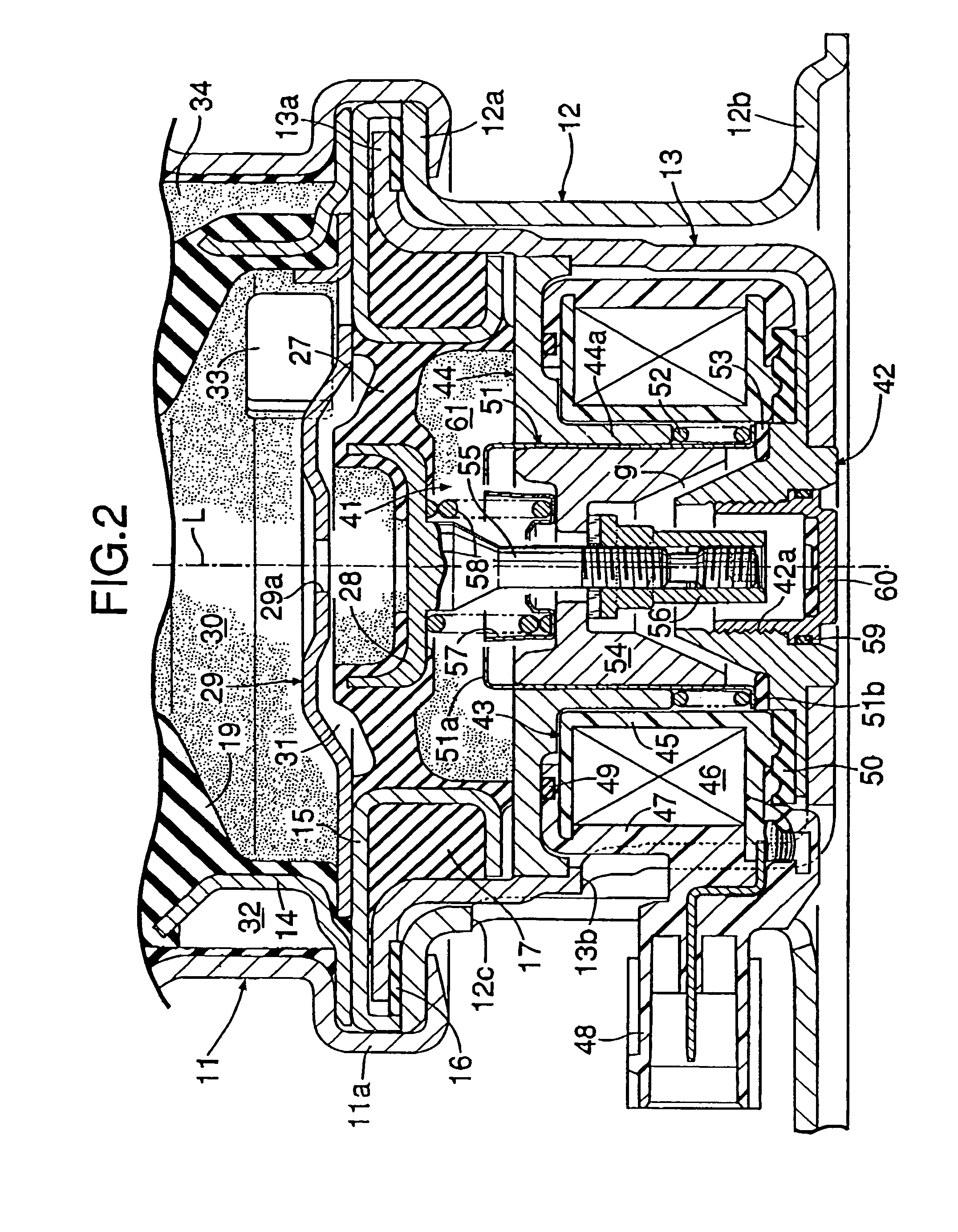
[0021]FIGS. 1 and 2 show an active vibration isolation support system M (an active vibration control mount) used for elastically supporting an engine on a vehicle body frame of an automobile. The system M substantially has an axially symmetric structure with respect to an axis L. Between a flange portion 11a provided at a lower end of a substantially cylindrical upper housing 11 and a flange portion 12a provided at an upper end of a substantially cylindrical lower housing 12; a flange portion 13a at an outer periphery of a substantially cup-shaped actuator case 13 with its upper face opened, an outer peripheral portion of an annular first-elastic-member supporting ring 14, and an outer peripheral portion of an annular second-elastic-member supporting ring 15 are superposed on and coupled to one another by crimping. In this structure, an annular first floating rubber ...


PUM


Abstract

An active vibration isolation support system includes an electronic control unit which supplies a target electric current to an actuator to periodically drive the actuator in an expansion and contraction manner with a target vibration waveform. The controller sets the target electric current by synthesizing a driving primary electric current waveform corresponding to the target vibration waveform for the actuator with higher-order (driving secondary and / or tertiary) electric current waveforms which eliminate higher-order vibration components of the actuator corresponding to the driving primary electric current waveform. It is possible to alleviate a calculating load in the electronic control unit by ignoring the quaternary and still higher-order vibration components which less affect the target vibration waveform for the actuator.

Description

RELATED APPLICATION DATA[0001]Japanese priority application No. 2004-240916, upon which the present application is based, is hereby incorporated in its entirety herein by reference.BACKGROUND OF THE INVENTION[0002]1. Field of the Invention[0003]The present invention relates to an actuator drive control device comprising a controller and an actuator, the controller supplying a target electric current to the actuator to periodically drive the actuator in an expanding and contracting manner with a target vibration waveform.[0004]2. Description of the Related Art[0005]Japanese Patent Application Laid-open No. 2002-139095 discloses an actuator drive control device, in which the driving cycle of an actuator is divided into a large number of very small time regions, and the duty ratios of the very small time regions are individually controlled, in order to drive a movable member of an active vibration isolation support system with a vibration waveform of a sine wave shape, so that a target...

Claims


Application Information

Patent Timeline
Patent Type & Authority Patents(United States)
IPC IPC(8): H02K33/00
CPCF16F13/26F16F15/00
Inventor NEMOTO, HIROTOMIISHIGURO, TETSUYA
Owner HONDA MOTOR CO LTD
Why Eureka
Try Eureka