

Residual current device
a current device and resistor technology, applied in the direction of relays, emergency protective arrangements for limiting excess voltage/current, emergency protective arrangements for automatic disconnection, etc., can solve the problems of complex electronic circuitry and components, and high impedance of rla coils
- Summary
- Abstract
- Description
- Claims
- Application Information
AI Technical Summary
Benefits of technology
Problems solved by technology
Method used
Image

Examples
Embodiment Construction
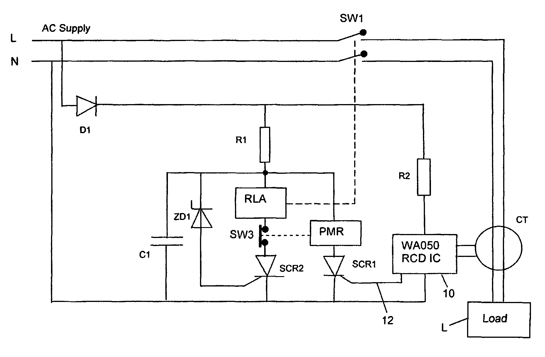
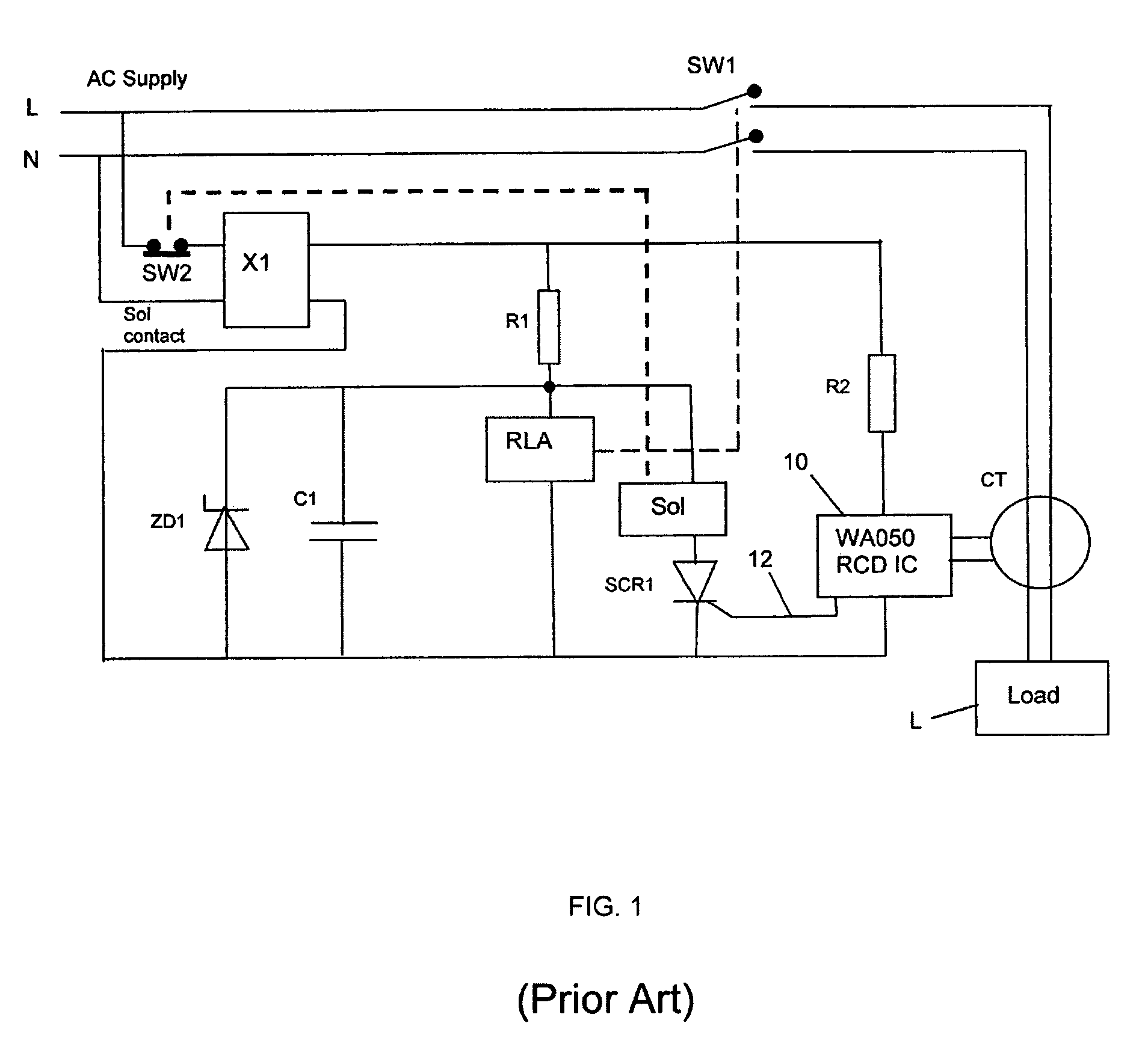
[0040]The embodiment shown in FIG. 3 mitigates the drawbacks of the arrangement of FIG. 1, and provides additional benefits.
[0041]In FIG. 3 the RCD is powered via a diode D1 rather than a bridge rectifier. The solenoid SOL has been replaced by a permanent magnet relay PMR. The PMR contacts SW3 and a second silicon controlled rectifier SCR2 are connected in series with the relay RLA. A Zener diode ZD2 is connected between C1 and the gate of SCR2. The remainder of the circuit is substantially the same as that shown in FIG. 1. A schematic diagram of the PMR is shown in FIG. 4.
[0042]The PMR comprises a bobbin 30 and a coil 32 wound on the bobbin. A ferromagnetic plunger 34 passes through the bore of the bobbin. One end of the plunger 34 is fitted with a reset button 36 which is biased downwardly (as seen in FIG. 4) by a reset spring 42. The other (upper) end of the plunger 34 faces a permanent magnet 44 to which is fixed a moving contact 38, the moving contact 38 being biased into an op...
PUM
 Abstract
Description
Claims
Application Information