Method and system for identifying an edge of a crop

a crop edge and crop technology, applied in the field of crop edge identification, can solve the problems of inability to provide location data in the vehicle, and inability to accurately identify the edge of the crop, etc., to achieve the effect of facilitating the guidance of the agricultural machin

Inactive Publication Date: 2011-03-29
DEERE & CO
View PDF87 Cites 83 Cited by
  • Summary
  • Abstract
  • Description
  • Claims
  • Application Information

AI Technical Summary

Benefits of technology

[0004]A method and system for identifying a crop edge of a crop facilitates guidance of an agricultural machine or other work vehicle along the crop edge at an interface between harvested and unharvested portions of a field. A transmitter emits a transmitted radiation pattern within a defined spatial zone. A receiver collects an image of the defined spatial zone. A detector detects a presence of the crop edge between a harvested and unharvested portion of a field based on an observed illumination radiation pattern on an unharvested portion. A data processor identifies coordinate data, in the collected image, associated with the detected crop edge.

Problems solved by technology

Although a work vehicle may be guided with a location-determining receiver (e.g., a Global Positioning System (GPS) receiver with differential correction), accurate location data to a desired degree of precision may be temporarily unavailable because of propagation problems (e.g., tree canopies) or other technical difficulties.
Further, some work vehicles may not be equipped with location-determining receivers that provide location data.

Method used


Image

  • Method and system for identifying an edge of a crop
  • Method and system for identifying an edge of a crop
  • Method and system for identifying an edge of a crop

Examples


Embodiment Construction

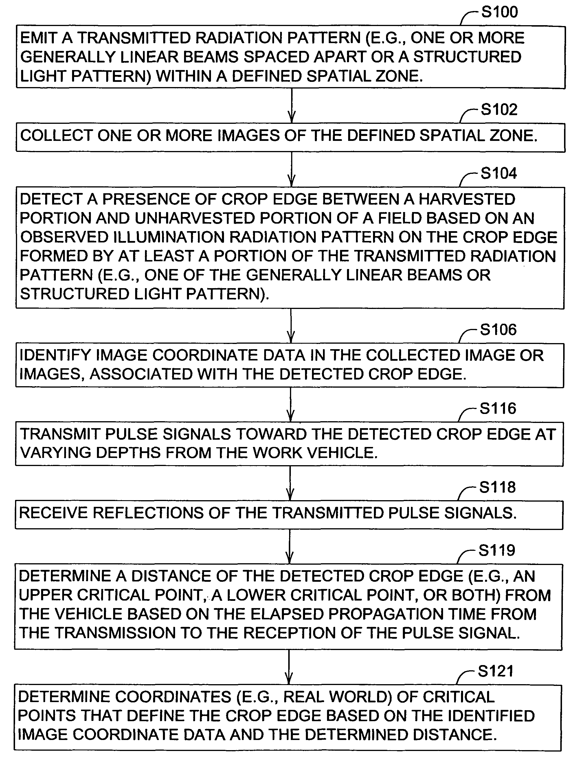
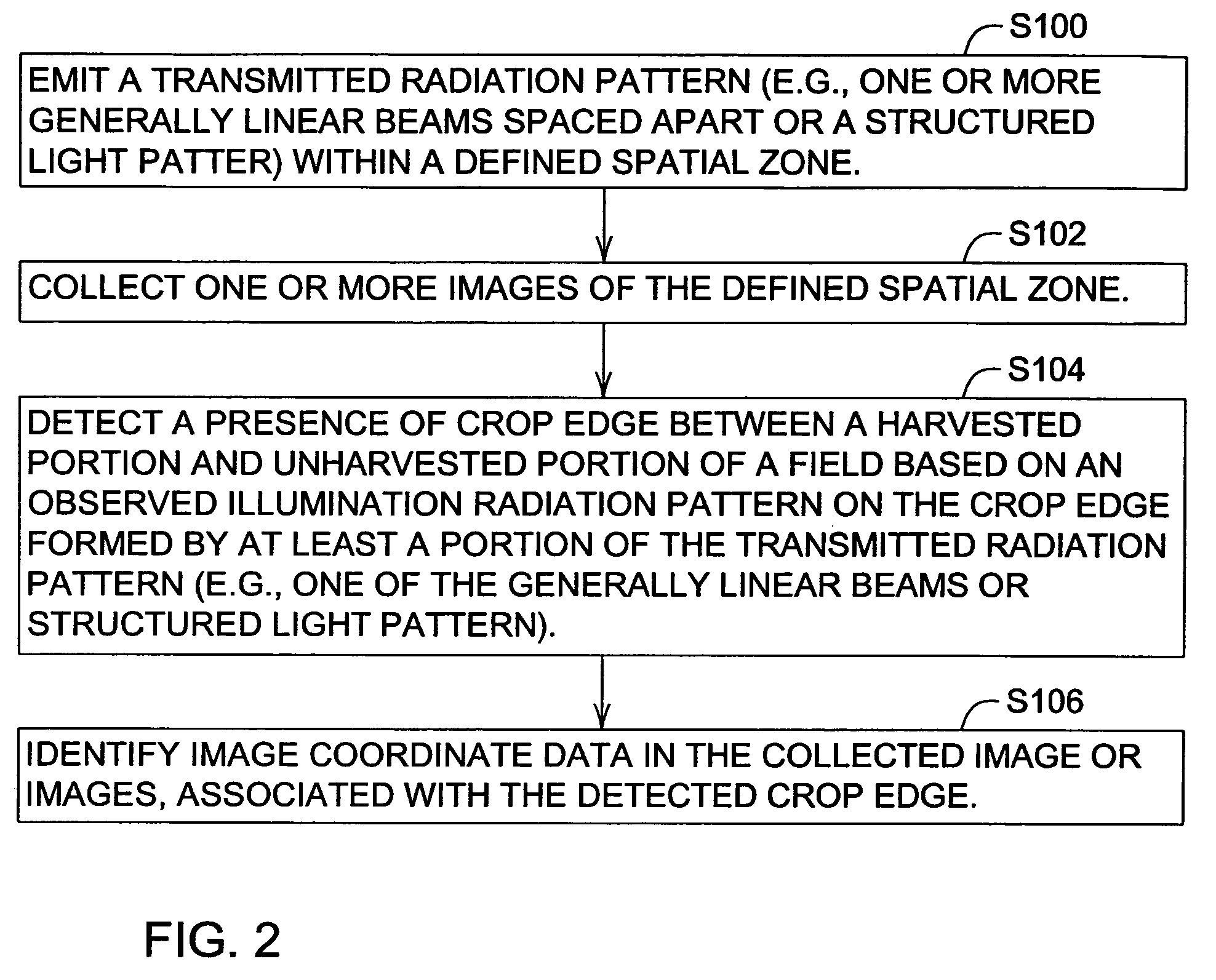
[0019]A crop edge may be defined by a group of points, segments or arcs that are interconnected. The crop edge may be defined in two dimensions or three dimensions. The crop edge may be defined by points, segments or arcs that lie on the ground or corresponding coordinates for such points, segments, or arcs. The crop edge may also be defined by a three-dimensional “wall” that is bound by an upper interface and a lower interface. Upper critical points lie on the upper interface, whereas lower critical points lie on the lower interface. Critical points shall refer to upper critical points, lower critical points, or both. Critical points may be expressed in three dimensional coordinates (e.g., Cartesian coordinates).

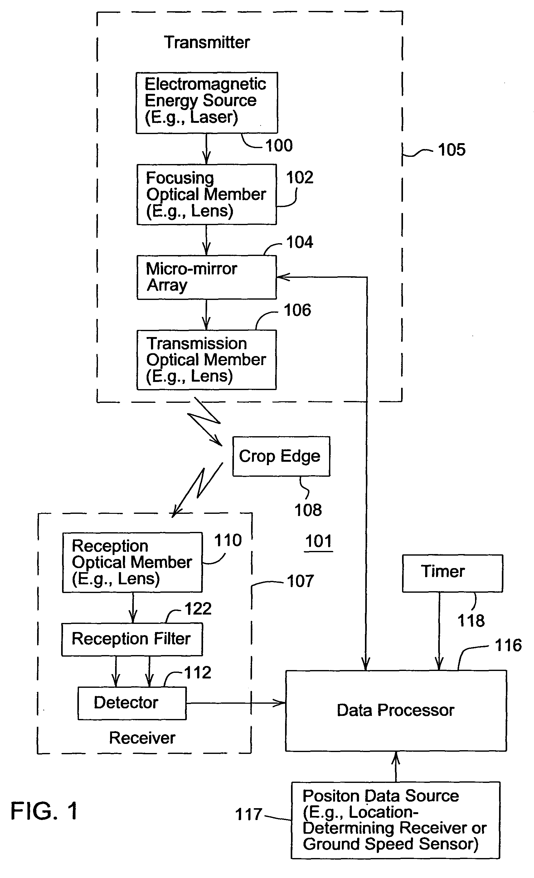
[0020]FIG. 1 shows a block diagram of an edge identification system 101 for determining location data or coordinates of an crop edge with respect to a reference point. The reference point may be defined with reference to the edge identification system 101 or a portion there...


PUM


Abstract

A method and system for identifying an edge of a crop facilitates guidance of an agricultural machine or other work vehicle along an edge of a crop at an interface between harvested and unharvested portions of a field. A transmitter emits a plurality of a transmitted radiation pattern of one or more generally linear beams spaced apart within a defined spatial zone. A receiver collects an image of the defined spatial zone. A detector detects a presence of crop edge between a harvested and unharvested portion of a field based on an observed illumination radiation pattern on the unharvested portion formed by at least one of the generally linear beams. A data processor identifies coordinate data, in the collected image, associated with the detected crop edge.

Description

[0001]This is a continuation-in-part of U.S. application Ser. No. 10 / 662,865, filed Sep. 15, 2003, now U.S. Pat. No. 6,839,127 and entitled OPTICAL RANGE FINDER HAVING A MICRO-MIRROR ARRAY.FIELD OF THE INVENTION[0002]This invention relates to a method and system for identifying an edge of a crop for guidance of an agricultural machine or another work vehicle.BACKGROUND OF THE INVENTION[0003]A work vehicle may comprise a combine, a harvester or another work vehicle for harvesting a crop. As crop is harvested, a boundary or edge is formed between the harvested and unharvested crop. The edge may form a generally linear path or a contour that is parallel to previous swaths of the work vehicle in the field, for example. Although a work vehicle may be guided with a location-determining receiver (e.g., a Global Positioning System (GPS) receiver with differential correction), accurate location data to a desired degree of precision may be temporarily unavailable because of propagation proble...

Claims


Application Information

Patent Timeline
Patent Type & Authority Patents(United States)
IPC IPC(8): G06K9/00G06F19/00G05D1/02G01C3/08G05B19/18H04N7/18G02B26/00A01D34/13A01D34/18G01S7/481G01S15/89G01S17/10G01S17/42G01S17/89
CPCA01B69/008A01D34/001A01D41/127A01D41/1278G01C3/08G01S7/4814G01S7/4817G01S17/10G01S17/42G01S17/89
Inventor ANDERSON, NOEL WAYNE
Owner DEERE & CO
Why Eureka
Try Eureka