Engine hydrocarbon adsorber

a technology of hydrocarbon adsorber and engine, which is applied in the direction of machines/engines, combustion-air/fuel-air treatment, and separation processes, etc., can solve the problems of unintentional increase of airflow restrictions, system unacceptably increased air flow restrictions, and operators tampering with flow restricting components, etc., to achieve superior purging and reduce the impact of flow restriction

Active Publication Date: 2011-04-05
FORD GLOBAL TECH LLC
View PDF30 Cites 16 Cited by
  • Summary
  • Abstract
  • Description
  • Claims
  • Application Information

AI Technical Summary

Benefits of technology

[0004]Thus in one approach, a hydrocarbon adsorbing arrangement for an internal combustion engine is provided. The hydrocarbon adsorbing arrangement may include an air intake tube having a cross-sectional shape and configured within the engine. An internal structural element may be positioned within the air intake tube and may be configured to support the cross-sectional shape. A hydrocarbon adsorber may be disposed adjacent the internal structural element wherein a fluid containing hydrocarbons passing through the air intake tube can make contact with the hydrocarbon adsorber. This approach provides various options for placing the adsorber within the intake package, resulting in superior purging because the adsorber can be directly adjacent to the engine air flow, and reduces impact on flow restriction (horsepower loss).
[0005]In one particular aspect, the internal structural element may retain carbon coated paper within the air intake tube, yet expose the carbon coated paper via cut-outs, or windows in the internal structure. In this way, the structural element, which may be a plastic insert, can not only maintain the cross section of a flexible clean air tube open during high air flow and high heat operating conditions, but also function to collect hydrocarbons during at least engine-off conditions.

Problems solved by technology

Some devices impose flow restrictions in the air intake to provide sufficient adsorption, while others do not.
However the inventors herein have recognized a number of issues with such approaches.
For example, some systems may unacceptably increase air flow restrictions in order to provide sufficient hydrocarbon adsorption.
Further still, operators may tamper with flow restricting components by removing the adsorber components without the removal being obvious.
As yet another example, there may be issues related to degradation of mechanical actuation to close and / or open air intake system components, possibly resulting in unintentional increased airflow restrictions, or both.

Method used


Image

  • Engine hydrocarbon adsorber
  • Engine hydrocarbon adsorber
  • Engine hydrocarbon adsorber

Examples


Embodiment Construction

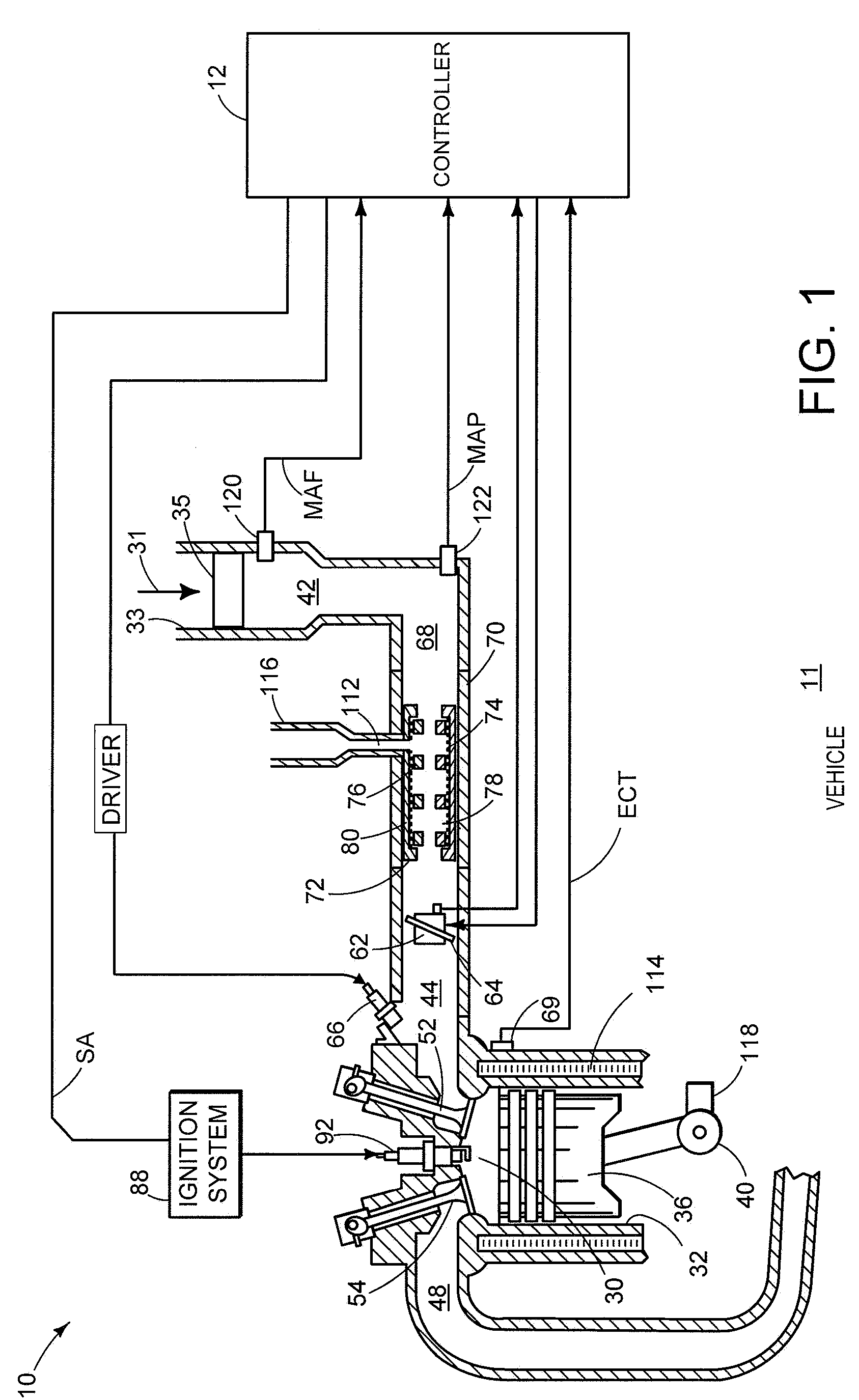
[0017]FIG. 1 is a schematic diagram showing one cylinder of multi-cylinder engine 10, which may be included in a propulsion system of a vehicle 11, or other commercial device. Engine 10 may be controlled at least partially by a control system including controller 12, and / or by input from a vehicle operator via an input device such as an accelerator pedal. Combustion chamber (i.e. cylinder) 30 of engine 10 may include combustion chamber walls 32 with piston 36 positioned therein. Piston 36 may be coupled to crankshaft 40.

[0018]Combustion chamber 30 may receive intake air 31 from intake manifold 44 via intake passage 42 and may exhaust combustion gases via exhaust passage 48. Intake manifold 44 and exhaust passage 48 can selectively communicate with combustion chamber 30 via respective intake valve 52 and exhaust valve 54.

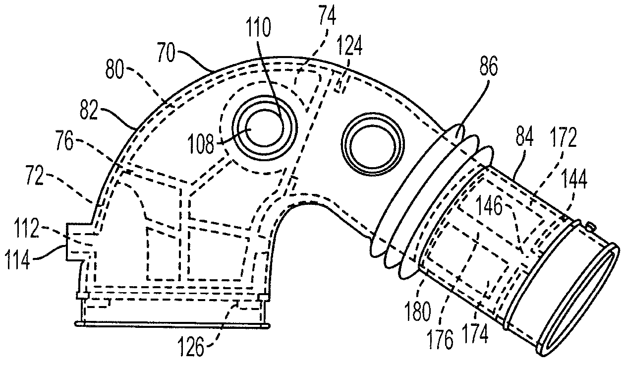
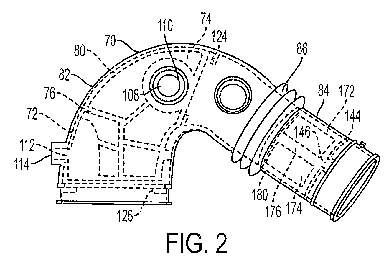
[0019]Intake air 31 may enter the intake manifold 44 via an inner passage 68 of an intake air duct such as a clean air tube 70. The clean air tube 70 may be downstre...


PUM

PropertyMeasurementUnit
cross-sectional shapeaaaaaaaaaa
lengthaaaaaaaaaa
circumferenceaaaaaaaaaa

Abstract

Devices, systems and methods are provided for adsorbing hydrocarbons from the air intake system of an internal combustion engine. The devices, systems and methods include a hydrocarbon absorbent material, and a structural element configured to hold the hydrocarbon absorbent material within a clean air tube of an internal combustion engine.

Description

BACKGROUND AND SUMMARY[0001]Hydrocarbon vapor emissions from an engine air intake system of a vehicle may be captured in adsorbing systems.[0002]Example devices adsorb these hydrocarbons when the engine is shut off. The hydrocarbons are desorbed and burned in the engine when the engine is operating. Hydrocarbon loading and purging cycles may continue throughout the useful life of the vehicle. Some devices impose flow restrictions in the air intake to provide sufficient adsorption, while others do not. Some systems utilize various extra valves and / or ducts to open / close and / or expose adsorbing elements only under selected conditions.[0003]However the inventors herein have recognized a number of issues with such approaches. For example, some systems may unacceptably increase air flow restrictions in order to provide sufficient hydrocarbon adsorption. Further still, operators may tamper with flow restricting components by removing the adsorber components without the removal being obvio...

Claims


Application Information

Patent Timeline
Patent Type & Authority Patents(United States)
IPC IPC(8): B01D59/50
CPCF02M25/0854F02M35/10144F02M35/1038F02M35/02
Inventor TOMLIN, JACQUELINEKHAMI, ROGERMOYER, DAVID S.CASSELL, HOVIE JARRETTROHRER, III, WILLIAM A.
Owner FORD GLOBAL TECH LLC
Why Eureka
Try Eureka