Apparatus and method to identify targets through opaque barriers

a target identification and opaque barrier technology, applied in the field of apparatus and methods to identify targets through opaque barriers, can solve problems such as increasing likelihood, and achieve the effects of preventing the ability to identify targets, improving prior art, and improving the performance of automatic target recognition

Inactive Publication Date: 2011-04-05
REALTRONICS CORP
View PDF37 Cites 32 Cited by
  • Summary
  • Abstract
  • Description
  • Claims
  • Application Information

AI Technical Summary

Benefits of technology

[0036]The disclosed invention is a method and apparatus for discriminating objects of interest from background clutter; particularly in environments where the desired target is occluded by walls and other opaque barriers. In an optimal embodiment of this invention, a sliding windowing function analyzes every portion of the radar signal. Time amplitude peaks in the radar return signature are used to dynamically position the windowing function as it is slid through the signal. This increases the likelihood that the entire portion of the signal that is distorted by the target is encompassed by the windowing function. A sufficiently small increment is used to ensure windowing function overlap throughout the entire reflected signal analysis. Characterization is further improved by capitalizing on the impact that distance between the sensor and the target has on the spectral composition and time amplitude decay of the energy in each windowing function. Both serve as orthogonal feature vector components that are combined uniquely by this invention with the dynamically selected time position of the windowing function in the reflected radar return to simultaneously improve false alarm mitigation and probability of detection rates.

Problems solved by technology

This increases the likelihood that the entire portion of the signal that is distorted by the target is encompassed by the windowing function.

Method used


Image

  • Apparatus and method to identify targets through opaque barriers
  • Apparatus and method to identify targets through opaque barriers
  • Apparatus and method to identify targets through opaque barriers

Examples


Embodiment Construction

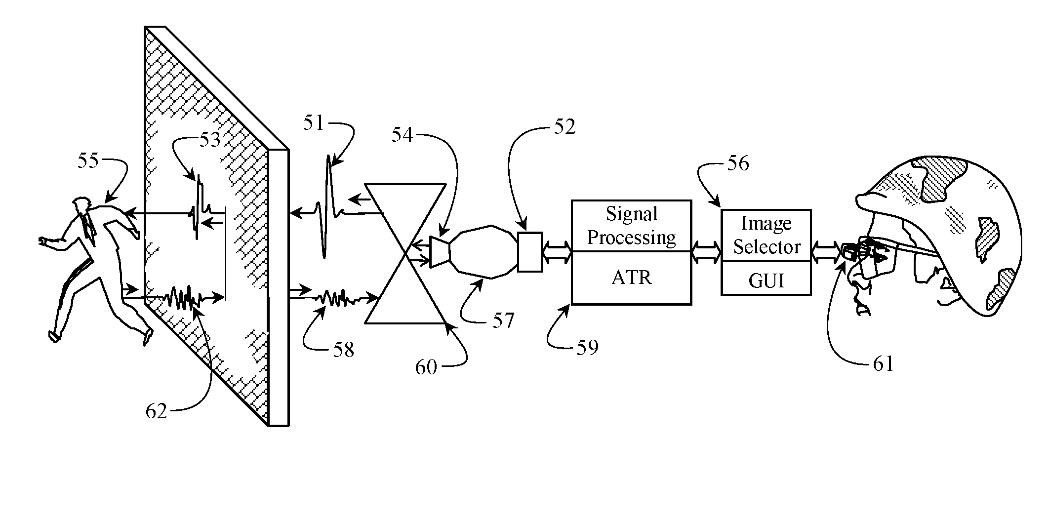
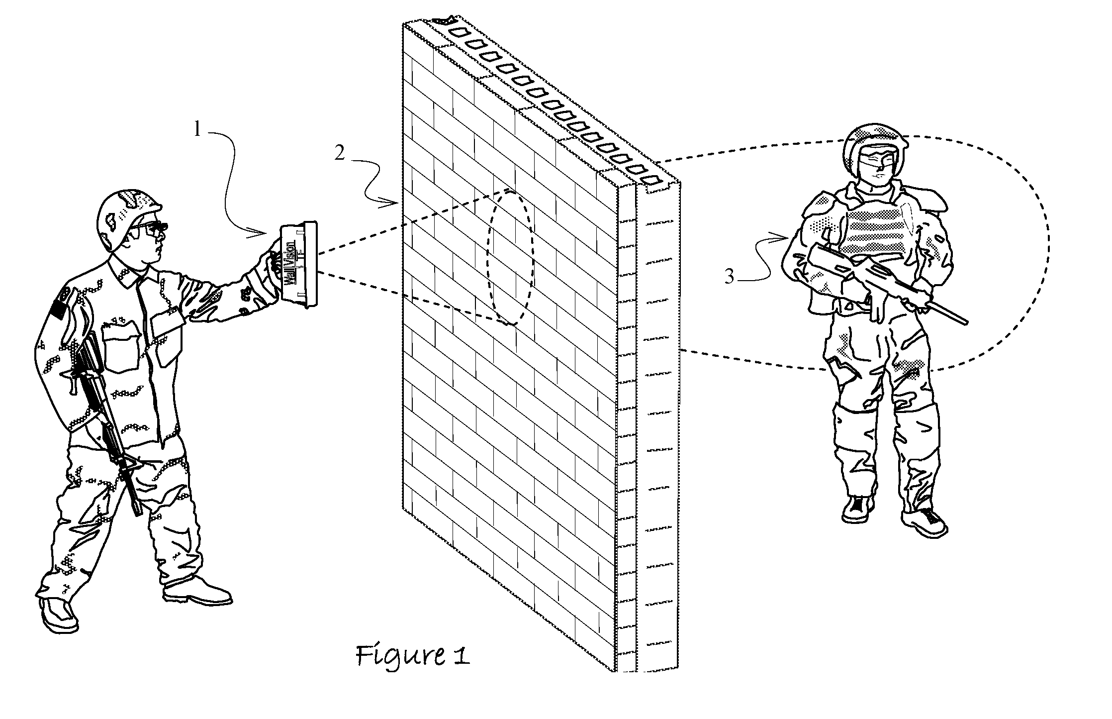
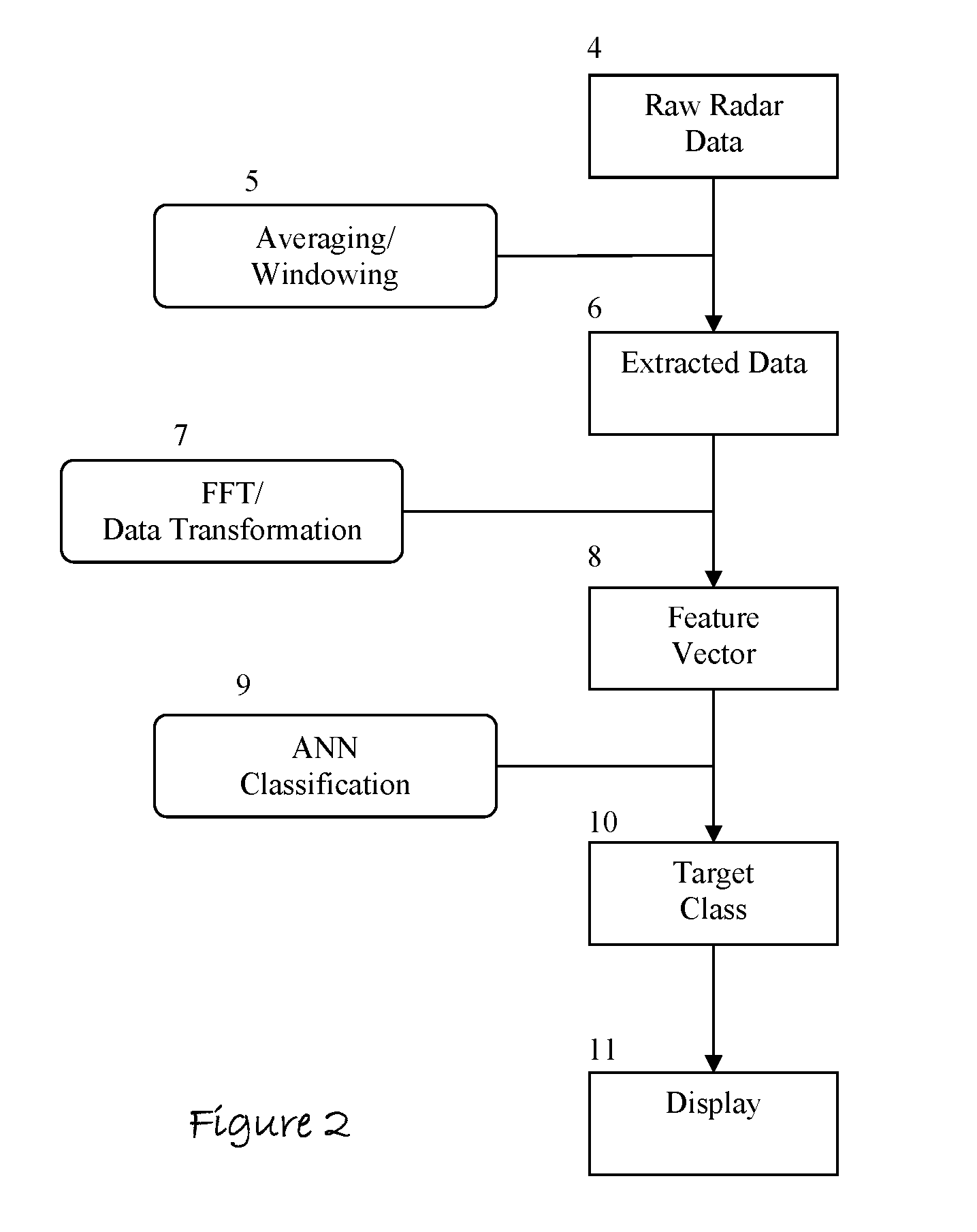
[0057]Preferred embodiments of this invention are illustrated in FIG. 1 and in FIGS. 3 through 7. The preferred method of operation comprises iteratively of collecting ultra wideband radar data by aiming an assembled embodiment of this invention 1 toward a wall 2 or other opaque barrier and by horizontally and vertically swaying the unit to search for objects of interest 3 that are concealed in or by the occlusion 2. The raw radar data 4 is subsequently provided to a signal processor where signal noise reduction techniques like signal averaging 5 are applied to the same. A windowing function 5 incrementally moves over the processed radar return signal to group the entire processed signal into individual elements 6 that can be closely examined for objects of interest. As the windowing function progresses through the processed signal, its position is dynamically centered over time domain amplitude magnitude peaks in the reflected return.

[0058]A FFT 7 is computed of each incremental an...


PUM


Abstract

The present invention is a method and apparatus that provides detection, characterization, and intuitive dissemination of targets. This disclosure combines improvements to ultra-wideband (UWB) sensing and machine target characterization with a means to convey data in a format that is quickly and readily understood by practitioners of the technology. The invention is well suited for Situational Awareness (SA) support in areas that are occluded by rain, fog, dust, darkness, distance, foliage, building walls, and any material that can be penetrated by ultra-wideband RF signals. Sense Through The Wall (STTW) performance parameters including target range, stand-off distance, and probability of detection are improved herein by combining a dynamically positioned sliding windowing function with orthogonal feature vectors that include but are not limited to time amplitude decay, spectral composition, and propagation time position in the return signal data. This invention is particularly useful for STTW and SA applications including urban combat, law enforcement, fire protection, transportation security, and homeland security. The invention can also be used to detect objects that are concealed by clothing, debris, and other non-metallic materials.

Description

CROSS REFERENCE TO RELATED APPLICATIONS[0001]This application is related to co-pending U.S. patent application Ser. No. 11 / 964,041, filed Dec. 26, 2007 and titled “Method and Apparatus to Display Actionable Radar Targets and Target Environments”, which claims the benefit of priority under 35 U.S.C. 119(e) to provisional application No. 60 / 871,859 filed Dec. 26, 2006 and titled “Method and Apparatus to Display Target Environments from Sense-Through-The-Wall Radar Data”. Related U.S. patent application Ser. No. 11 / 964,041 further claims the benefit of priority under 35 U.S.C. 120, to related U.S. patent application Ser. No. 11 / 164,173, filed Nov. 14, 2005, now U.S. Pat. No. 7,339,516, issued Mar. 4, 2008 and titled “Method to Provide Graphical Representation of Sense Through The Wall (STTW) Targets” and further claims benefit of priority under 35 U.S.C. 119(e) to provisional application No. 60 / 595,870 filed Aug. 11, 2005 and titled “Method to Provide Graphical Representation of STTW T...

Claims


Application Information

Patent Timeline
Patent Type & Authority Patents(United States)
IPC IPC(8): G01S13/04G01S7/483G01S7/00G01S13/10
CPCG01S7/414G01S13/89G01S13/888G01S7/417
Inventor THOMPSON, SCOTT RANDALLASKILDSEN, BERNT AGERVASI, ANTHONY
Owner REALTRONICS CORP
Why Eureka
Try Eureka