Steam-cooled gas turbine bucket for reduced tip leakage loss

a technology of gas turbines and buckets, which is applied in the direction of liquid fuel engines, machines/engines, reaction engines, etc., can solve the problems of impeded tip leakage loss, fluid flow in the gas path, and the gap between the rotating bucket and the stationary shroud over the bucket, so as to achieve impede the effect of tip leakage loss

Inactive Publication Date: 2011-04-12
GENERAL ELECTRIC CO
View PDF16 Cites 10 Cited by
  • Summary
  • Abstract
  • Description
  • Claims
  • Application Information

AI Technical Summary

Benefits of technology

[0004]This invention, in one exemplary embodiment, seeks to provide various geometry features on the tip cap to impede tip leakage loss without degrading LCF and creep life of a closed-loop steam-cooled bucket.
[0005]In the exemplary embodiment, the thickness of a thermal barrier coating (TBC) material applied to the bucket tips (references to the “tips” include the welded-on tip cap unless otherwise noted) is increased sufficiently to allow a cavity to be machined or ground into the TBC coating in the bucket tip center portion, along the main camber line of the tip. The cavity therefore also defines a ridge about the perimeter of the bucket (at the edge or offset from the edge), along both the suction and pressure surfaces, similar to a conventional squealer tip. A ridge formed along only the pressure side, or only the suction side of the airfoil is also contemplated. In still another variation, a single ridge may be formed along the mean camber line of the TBC-coated bucket tip for the purpose of effectively reducing the tip gap over a rotating unshrouded bucket.
[0006]By machining or grinding (or otherwise resurfacing by any suitable means) these or similar geometries into the thermal barrier coating applied to the bucket tip, the flow of fluid in the gas path from the pressure surface to the suction surface through the tip gap between the rotating bucket and the stationary shroud over the bucket is impeded. The thermal barrier coating also reduces the heat flux into the bucket tip base metal. The reduction in heat flux will reduce the thermal gradient through the base metal of the tip. This reduction in thermal gradient significantly enhances the LCF and creep life of the bucket tip.
[0009]In still another aspect, the present invention relates to a method of reducing tip leakage loss at a radially outer tip of a turbine bucket comprising: (a) coating the radially outer tip of the bucket with a thermal barrier coating; (b) resurfacing the thermal barrier coating to include at least one tip leakage loss feature in the coating, extending substantially the entire length of the tip.

Problems solved by technology

By machining or grinding (or otherwise resurfacing by any suitable means) these or similar geometries into the thermal barrier coating applied to the bucket tip, the flow of fluid in the gas path from the pressure surface to the suction surface through the tip gap between the rotating bucket and the stationary shroud over the bucket is impeded.

Method used


Image

  • Steam-cooled gas turbine bucket for reduced tip leakage loss
  • Steam-cooled gas turbine bucket for reduced tip leakage loss
  • Steam-cooled gas turbine bucket for reduced tip leakage loss

Examples


Embodiment Construction

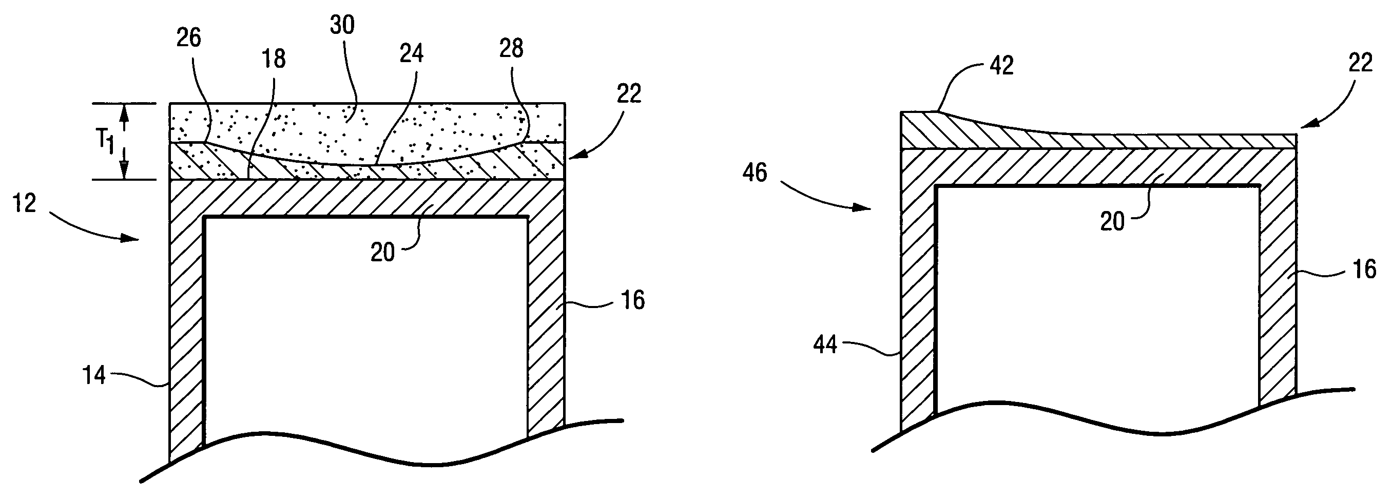
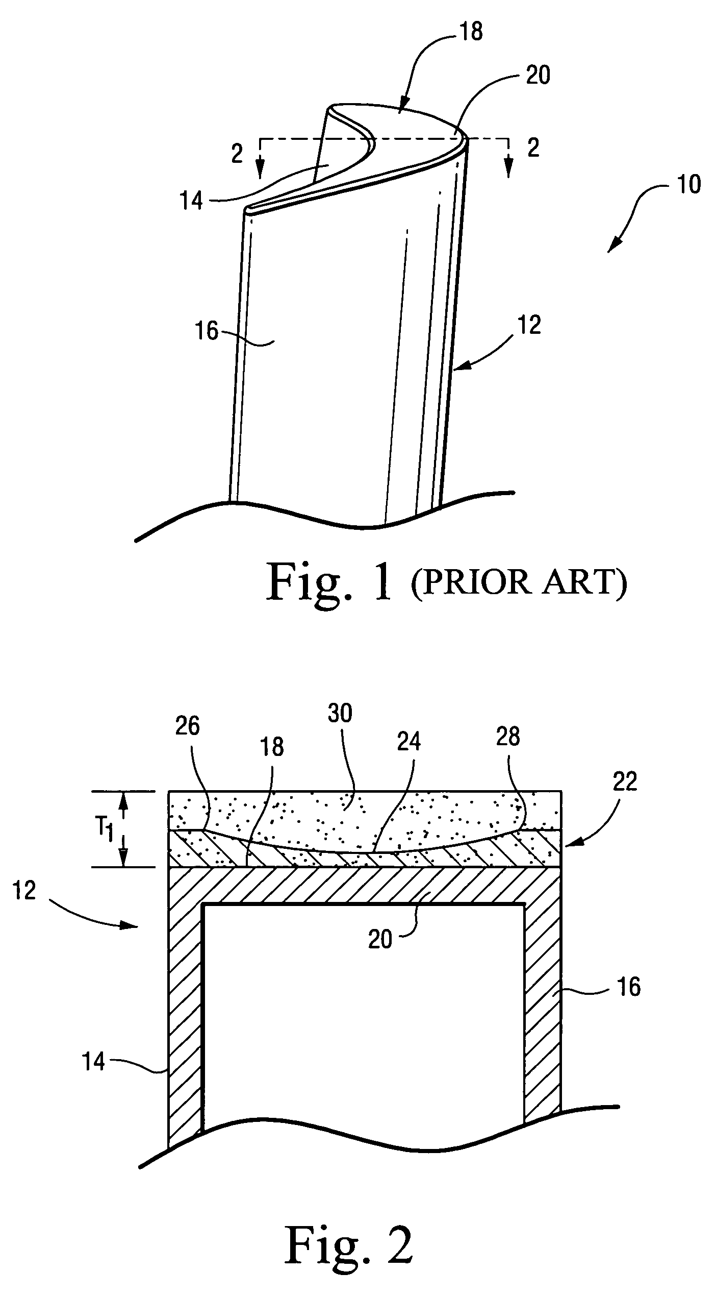
[0016]FIG. 1 illustrates a conventional closed-circuit, steam-cooled bucket for a steam turbine first stage. The bucket 10 is formed with an airfoil portion 12 including a pressure surface (or side) 14 and a suction surface (or side) 16. The radially outer tip 18 of the bucket is closed by a tip cap 20 that is welded in place and subsequently sprayed with an otherwise conventional thermal barrier coating (TBC) 22 (FIG. 2). Platform and mounting (e.g., dovetail) portions (not shown) of the bucket are otherwise conventional and need not be described.

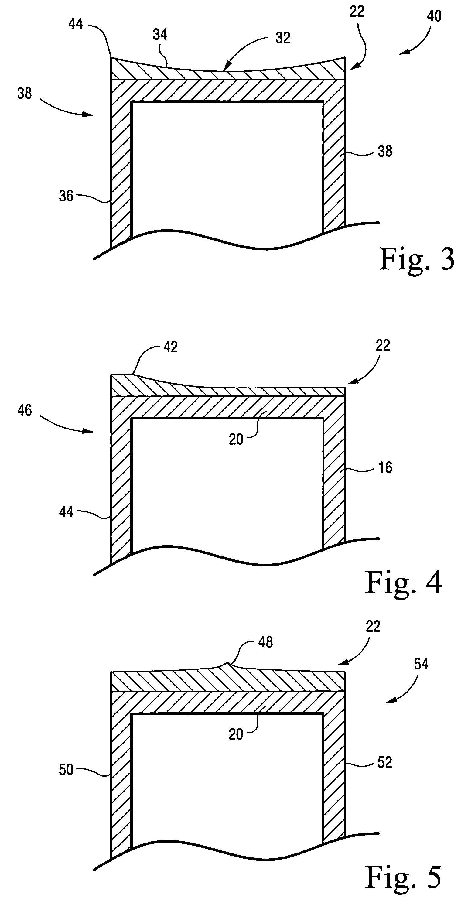
[0017]In the example portrayed in FIG. 2, the thermal barrier coating 22 is increased in thickness to T1 in order to provide sufficient coating material to accommodate a tip leakage loss-reduction feature as explained below. More specifically, in the FIG. 2 example, the coating 22 is machined to reduce the overall thickness of the coating and to form a cavity 24 in the center region of the tip cap, running along the mean camber line of the...


PUM


Abstract

A bucket for a steam turbine includes an airfoil portion having a radially outer tip, the radially outer tip having a thermal barrier coating applied thereto, and wherein the thermal barrier coating is resurfaced to form at least one ridge along the radially outer tip.

Description

BACKGROUND OF THE INVENTION[0001]This invention relates to steam turbine buckets generally and to the incorporation of a tip leakage loss reduction feature in the thermal barrier coating applied to the bucket tip.[0002]The radially outer tips of gas turbine buckets serve in a hostile environment of both high temperature and high rotationally-induced stress. The life of parts subjected to these conditions is typically limited by low-cycle fatigue (LCF) and creep considerations. In accordance with conventional practice, a tip cap is welded to the bucket as part of a current manufacturing process for hot gas path sealing purposes. The addition of a conventional metal seal to the existing tip cap increases the thermal gradient at the tip, however, and therefore degrades the LCF and creep life. In prior art buckets, this is overcome by employing film cooling in the bucket tip region. In closed-loop steam-cooled turbine bucket applications, however, airfoil film cooling cannot be practica...

Claims


Application Information

Patent Timeline
Patent Type & Authority Patents(United States)
IPC IPC(8): F01D5/20
CPCF01D5/20F01D11/122F01D5/288
Inventor ITZEL, GARY MICHAELANDREW, PHILIP LYNN
Owner GENERAL ELECTRIC CO
Why Eureka
Try Eureka