Ferromagnetic shield for magnetic resonance imaging

a magnetic resonance imaging and magnetoelectric shield technology, applied in the field of magnetoelectric shielding, can solve problems such as noise sources, achieve the effects of improving the cooling performance of cryoelectric heaters, reducing noise sources, and increasing the life of cryoelectric heaters

Inactive Publication Date: 2011-04-12
KONINK PHILIPS ELECTRONICS NV
View PDF10 Cites 3 Cited by
  • Summary
  • Abstract
  • Description
  • Claims
  • Application Information

AI Technical Summary

Benefits of technology

[0018]Another advantage of the invention is that it enables a substantial reduction of the noise source listed above under item 2 by use of the shield of ferromagnetic material designed so that the change in magnetization caused by the inhomogeneous magnetic field along the path of the regenerator compensates the change in magnetization caused by the temperature change of the rare-earth material.
[0019]As mentioned above the shield of ferromagnetic material diminishes the magnitude and gradient of the local superconductive main magnetic field at the location of the rare-earth regenerator. As a consequence the main magnetic field exerts a diminished force on the moving magnetized rare-earth regenerator. Lower forces on the rare-earth regenerator lead to reduced forces on the displacer. This causes a smoother cycle of the displacer, which results in an improvement of the cooling performance of the cryocooler and additionally increases the cryocooler lifetime.
[0020]The arguments given above in favor of the use of the ferromagnetic shield are set forth in more detail in the following.
[0021]According to a preferred embodiment, the shield of ferromagnetic material is adapted to reduce the magnitude of the magnetic field generated by the superconductive magnet of the magnetic resonance imaging apparatus in the surrounding of the rare-earth regenerator. Taking into account that the relation between magnetization intensity of the rare-earth material with respect to temperature strongly depends on the magnetic field strength, a sufficient decrease in temperature sensitivity of the rare-earth material with respect to magnetization can be effectively achieved by making use of the ferromagnetic shield. For typical rare-earth materials such as e.g. Er3Ni, HoCu2 or ErNiCo, the slope of the curve representing the relation between magnetization level and temperature decreases with decreasing applied magnetic field. Additionally, the overall level of magnetization of the rare-earth material decreases accordingly.
[0022]Consequently, by making use of a ferromagnetic shield around the second stage of a two stage cryocooler, the magnetic field inside the cryocooler and hence around the rare-earth regenerator can be reduced to a minimum leading to a minimum impact of the rare-earth regenerator movement to the main magnetic field applied for magnetic resonance image acquisition.
[0023]In a further preferred embodiment, the shield of ferromagnetic material is adapted to reduce a spatial inhomogeneity of the magnetic field in the vicinity of the rare-earth regenerator. In contrast to conventional shielding materials, due to its ferromagnetic properties, the ferromagnetic material generally exhibits a more homogeneous magnetization level and thus effectively reduces the spatial inhomogeneity of the magnetic field along the moving path of the moveable rare-earth regenerator.

Problems solved by technology

The first source of noise is due to the change in distance of the magnetized rare-earth material with respect to the imaging volume caused by the reciprocating movement of the rare-earth material.

Method used


Image

  • Ferromagnetic shield for magnetic resonance imaging
  • Ferromagnetic shield for magnetic resonance imaging
  • Ferromagnetic shield for magnetic resonance imaging

Examples


Embodiment Construction

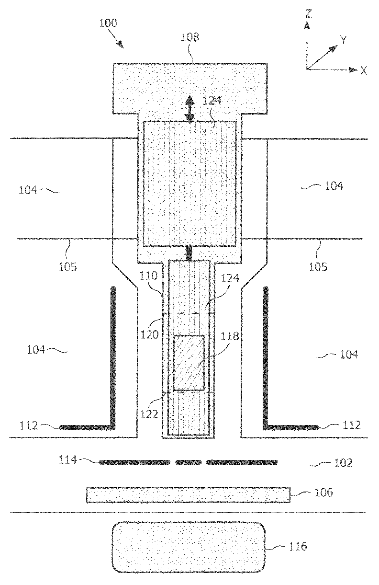
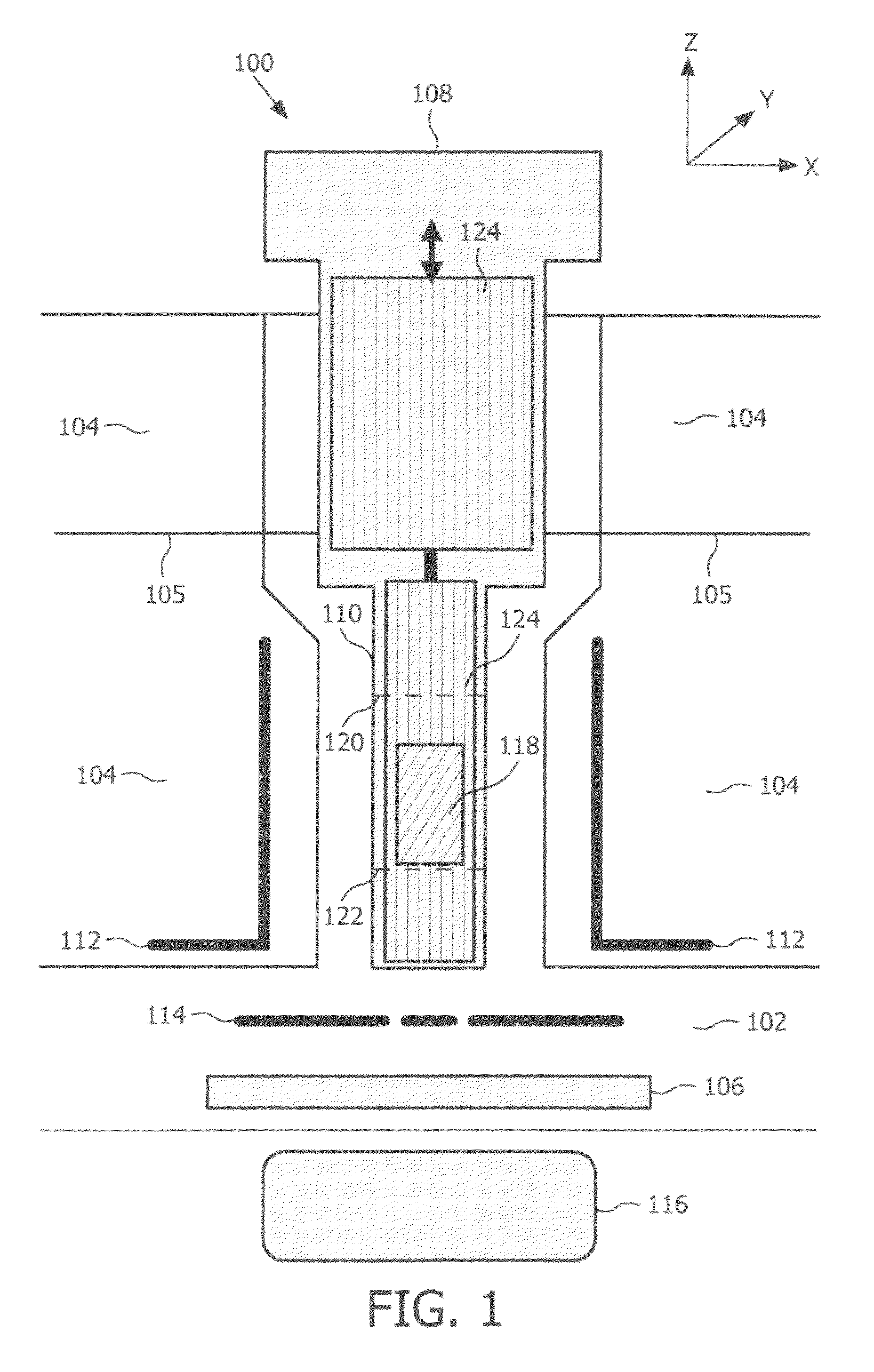
[0043]FIG. 1 illustrates a cross section of the cryocooler assembly 100, where the cryocooler 108 is located in the bore formed by the vacuum area 104. A radiation shield 105 at a temperature of about 20 Kelvin and located inside the vacuum area 104 shields the colder parts of the assembly, e.g. the cooling liquid reservoir 102, from thermal radiation. The second stage 110 of the cryocooler 108 featuring a narrow, slab like geometry whose distal end, i.e. the lower portion, is in thermal contact with the cooling liquid reservoir 102. The cooling liquid, which is e.g. liquid helium, provides cooling of the superconductive coil or superconductive magnet 106 for generating a highly uniform magnetic field for magnetic resonance imaging of an imaging area 116. As illustrated in the embodiment, the cryocooler assembly 100 has a ferromagnetic shield 112 surrounding the second stage 110 of the cryocooler 108 and hence surrounding the rare-earth regenerator 118.

[0044]The rare-earth regenerat...


PUM


Abstract

A cryocooler assembly includes a ferromagnetic shield and a moveable rare-earth regenerator for recondensing of a cooling liquid for cooling of a superconductive magnet of a magnetic resonance imaging apparatus. The ferromagnetic shield effectively provides depletion of a magnet field in the vicinity of the rare-earth regenerator and therefore on the one hand reduces the noise impact of the moving regenerator on the homogeneous magnetic field in the imaging volume of the MRI apparatus and on the other hand reduces the mechanical force exerted by the magnetic field on the rare-earth regenerator.

Description

FIELD OF THE INVENTION[0001]The present invention relates to the field of magnetic resonance imaging and more particularly without limitation to magnetic shielding of a cryocooler of a magnetic resonance imaging system.BACKGROUND AND PRIOR ART[0002]Generation of magnetic fields for magnetic resonance imaging (MRI) typically makes use of superconductive coils providing a negligible electric resistance and thus a magnetic field of a required magnitude if supplied with an electric current. Superconductivity is typically achieved in a temperature region at a few Kelvin, e.g. in the range of 4 to 10 Kelvin, which is for instance around the boiling temperature of liquid helium. Once the magnet coil is cooled down to such a superconducting level, a current will continue to flow through the coil due to the negligible coil resistance even after the electric power supply is removed, thereby maintaining a strong, steady magnetic field.[0003]In typical magnetic resonance imaging systems, the ma...

Claims


Application Information

Patent Timeline
Patent Type & Authority Patents(United States)
IPC IPC(8): G01V3/00
CPCG01R33/3815G01R33/3804
Inventor AARTS, BENJAMIN HENDRICUS
Owner KONINK PHILIPS ELECTRONICS NV
Why Eureka
Try Eureka