X ray CT system

a ct system and x-ray technology, applied in the field of x-ray ct system, can solve the problems of difficult to achieve such automatic separation of compositions (materials), and achieve the effect of easy setting of x-ray conditions

Active Publication Date: 2011-04-12
FUJIFILM HEALTHCARE CORP
View PDF11 Cites 10 Cited by
  • Summary
  • Abstract
  • Description
  • Claims
  • Application Information

AI Technical Summary

Benefits of technology

[0010]In other words, the X-ray CT system according to a first aspect of the present invention includes, an X-ray irradiation unit for irradiating X-rays having multiple types of different energy spectra, an X-ray detection unit for detecting the X-rays after passing through an object, an image calculation unit for calculating an image of X-ray attenuation coefficients respectively for the multiple types of X-rays based on each detection signal from the X-ray detection unit, a separation calculator for applying to a separation map which indicates a relationship between multiple types of X-ray attenuation coefficients and a composition of the object, values of the X-ray attenuation coefficients in association with a corresponding area in the image of multiple types of X-ray attenuation coefficients, so that the composition of the area is separated, a map formation unit for separation to form the separation map, and an input unit for accepting from an operator an input regarding an X-ray irradiation condition of the X-ray irradiation unit and multiple compositions to be separated, wherein, the map formation unit for separation performs arithmetic processing to obtain existing probabilities of the multiple compositions under the X-ray irradiation condition being inputted in the input unit, and forms the map for separation based on the existing probabilities. As thus described, the X-ray CT system according to the first aspect of the present invention is able to form the map for separation in response to the X-ray condition being inputted in the input unit, and therefore, separation of the composition can be performed with a high degree of accuracy by the use of an optimum map for separation.
[0105]In the present invention, as in the first embodiment and the second embodiment, it is possible to form an optimum map for separation based on the imaging condition such as a separated target region and X-ray tube voltage. Therefore, a high degree of separation accuracy can be achieved by applying the optimum map for separation. Further, as in the third embodiment, it is also possible to calculate an optimum X-ray condition, and therefore reduction of dose can also be achieved.

Problems solved by technology

However, it is sometimes difficult to achieve such automatic separation of compositions (materials) which include X-ray attenuation coefficients being close to each other, as in the case of bone, organs, and vessels of a clinical material, for instance.

Method used


Image

  • X ray CT system
  • X ray CT system
  • X ray CT system

Examples


first embodiment

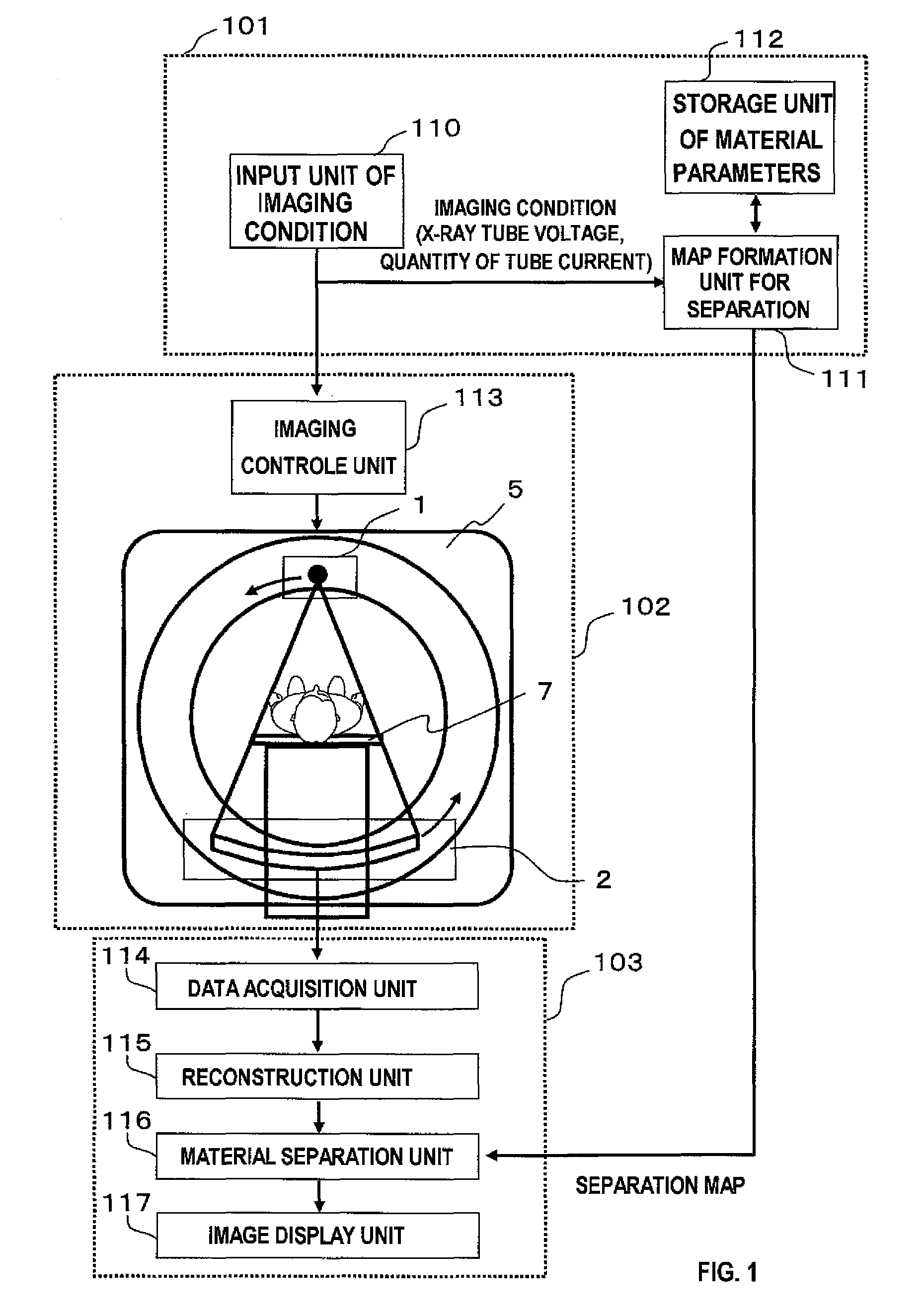
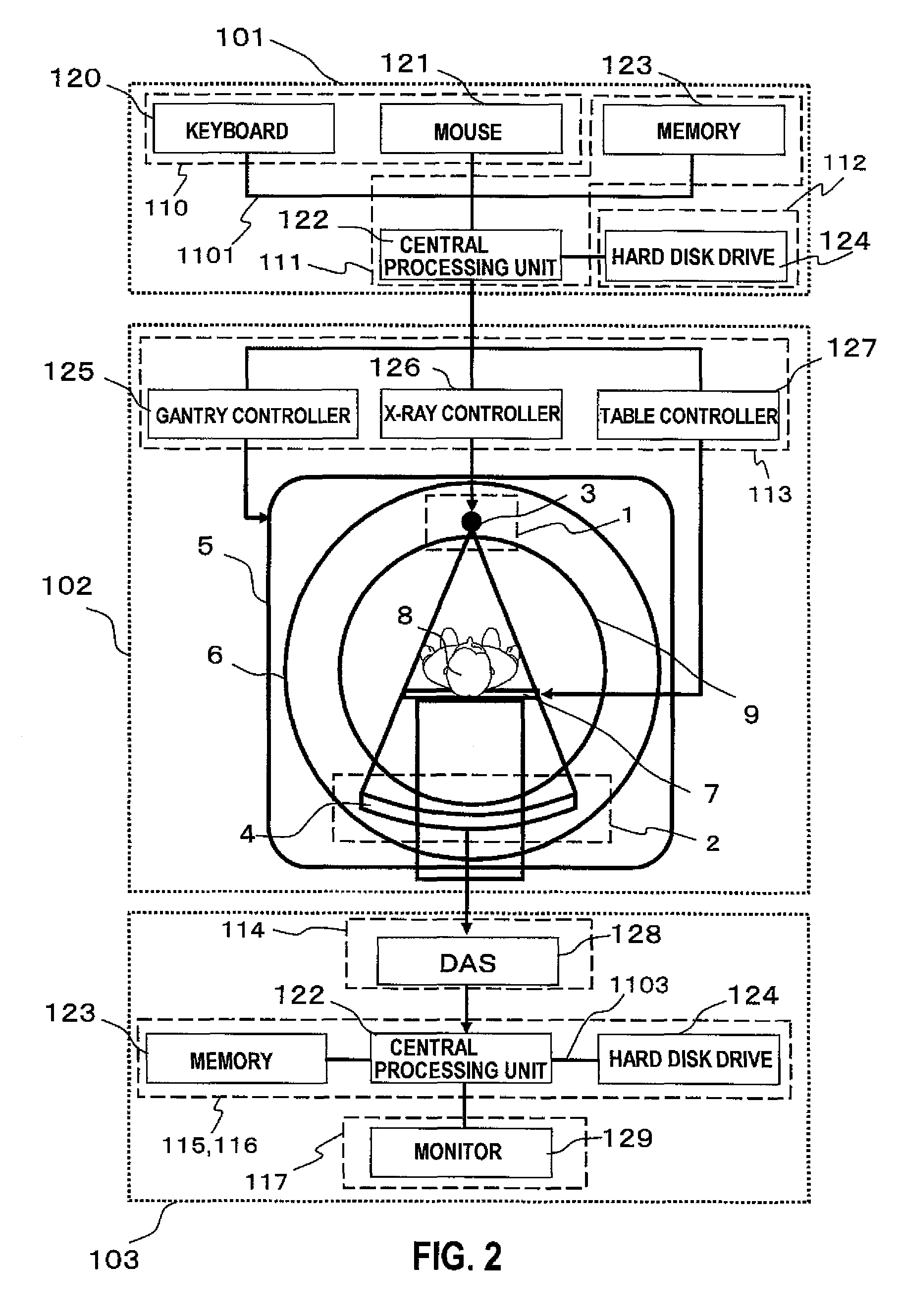
[0023]A dual energy X-ray CT system according to the first embodiment will be explained. As shown by the schematic configuration of FIG. 1, the X-ray CT system incorporates an input means 101, an imaging means 102, and an image generation means 103. The input means 101 includes an input unit of imaging condition 110, a map formation unit for separation 111, and a storage unit of material parameters 112. The imaging means 102 includes an imaging control unit 113, an X-ray irradiation unit 1, an X-ray detection unit 2, a gantry 5, and an object-installation table 7. The image generation means 103 includes a data acquisition unit 114, a reconstruction unit 115, a material separation unit 116, and an image display unit 117. It is to be noted here that the input means 101 and the image generation means 103 are not necessarily merged with the X-ray CT system, and such operations may be implemented by a second device which is connected via a network.

[0024]One example of hardware configurat...

second embodiment

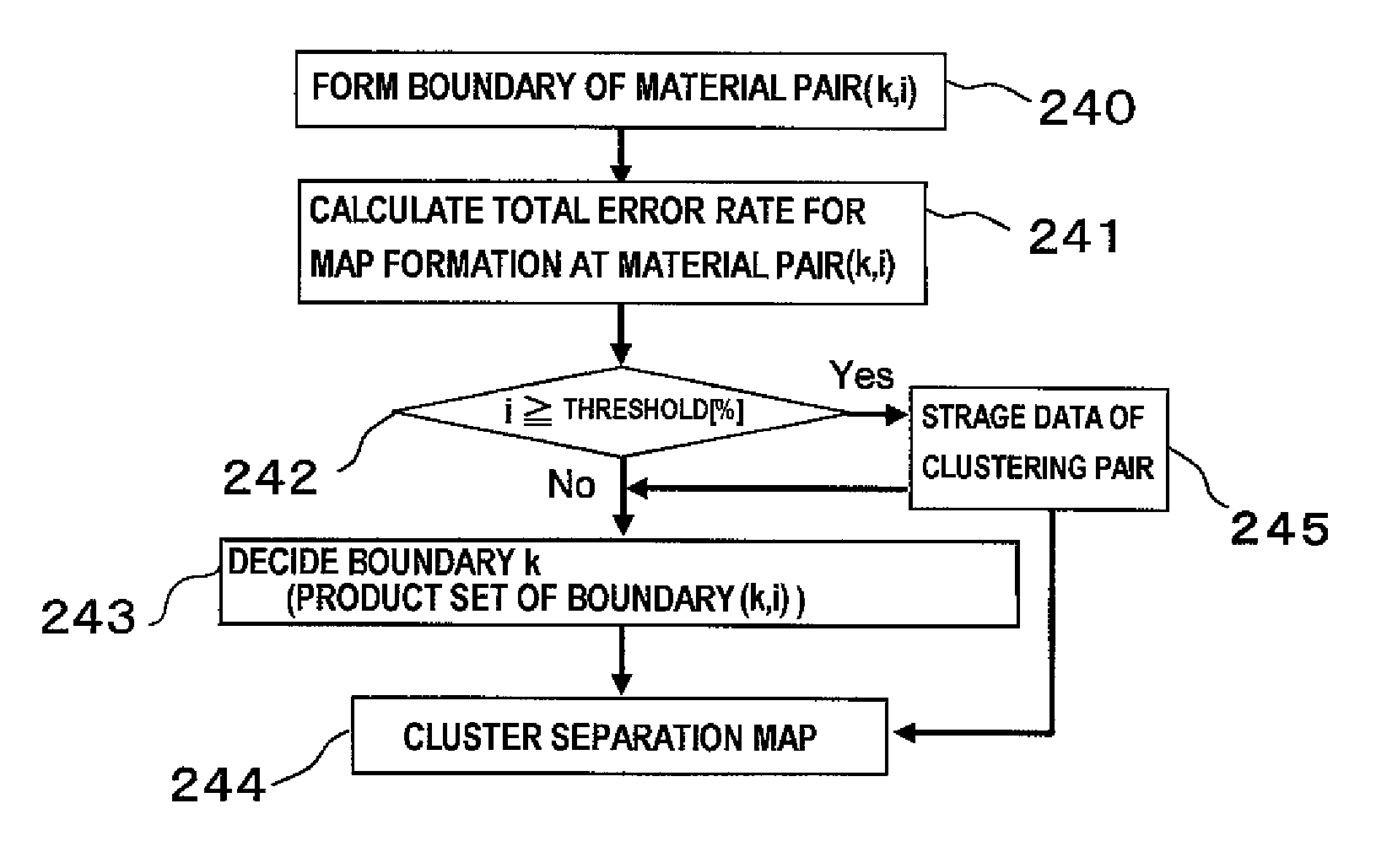
[0068]A dual energy X-ray CT system according to a second embodiment will be explained. The configuration of the X-ray CT system according to the present embodiment is the same as the X-ray CT system of the first embodiment, but an operation for forming the map for separation by the map formation unit for separation 111 is different from that of the first embodiment.

[0069]The first embodiment is directed to a configuration where the map formation unit for separation 111 forms a map for separation (e.g., FIG. 5) that is divided into N areas respectively corresponding to N materials, when the operator designates via the input unit of imaging condition 110, N materials as the areas to be separated. However, if there are materials having similar distribution of X-ray attenuation coefficient μ(x, y), or the like, there is a possibility that the accuracy for separating two materials is low even though the formed map for separation is used. In such a case above, it is not possible to enhan...

third embodiment

[0081]The dual energy X-ray CT system according to a third embodiment enables an imaging under an optimum X-ray condition. In the CT system according to the third embodiment, it is not necessary for an operator to input all of the imaging condition such as the separated target region, material, and dose, and only a partial condition is inputted. As for the part of the imaging condition that is not designated by the operator, the X-ray CT system generates multiple candidate values different in conditions variously in types, and forms a map for separation for each candidate value to obtain separation accuracy. Accordingly, while satisfying the imaging condition desired by the operator, it is possible to calculate an optimum X-ray condition having the highest degree of separation accuracy. In the real imaging mode, imaging can be performed under the optimum X-ray condition being calculated.

[0082]A structure of the dual energy X-ray CT system according to the third embodiment is similar...


PUM


Abstract

The dual energy X-ray CT apparatus automatically optimizes a map for separation to achieve a high degree of separation accuracy and a reduction of dose.An X-ray attenuation coefficient acquired in the dual energy X-ray CT system is applied to a map for separation which represents a relationship between the X-ray attenuation coefficient and a composition of an object, thereby separating the composition of the object. The map formation unit for separation calculates an existing probability of each composition for each combination of multiple types of X-ray attenuation coefficients, and determines the composition having the largest existing probability as the composition corresponding to the combination of the X-ray attenuation coefficients, thereby forming the map for separation. This configuration allows a formation of the map for separation with respect to each imaging condition, and high degree of accuracy in separating composition can be achieved.

Description

TECHNICAL FIELD[0001]The present invention relates to an X-ray CT system, and more particularly, it relates to a technique for achieving a high degree of accuracy in separating a composition of an object, and a technique for reducing a dose.BACKGROUND ART[0002]An X-ray CT system is a device for measuring a computed tomographic image (hereinafter, referred to as “CT image”), and density of the image represents an X-ray attenuation coefficient (hereinafter, referred to as “attenuation coefficient”). According to a technological innovation of recent years, it is becoming possible to acquire a large quantity of CT images. As a result, in order to efficiently utilize the large quantity of CT images, it is of growing importance to have a function for automatically separating a composition of the object by the use of a computer. However, it is sometimes difficult to achieve such automatic separation of compositions (materials) which include X-ray attenuation coefficients being close to eac...

Claims


Application Information

Patent Timeline
Patent Type & Authority Patents(United States)
IPC IPC(8): A61B6/00
CPCA61B6/032A61B6/405A61B6/482A61B6/4241A61B6/583
Inventor YAMAKAWA, KEISUKEUEKI, HIRONORI
Owner FUJIFILM HEALTHCARE CORP
Why Eureka
Try Eureka