Heating unit and method of making the same

a technology of heat exchanger and heat exchanger, which is applied in the direction of electrographic process, instrument, and semiconductor/solid-state device details, etc., can solve the problems of surge issue, insufficient insulation performance, and critical surge issues, and achieve the effect of suppressing reaction

Inactive Publication Date: 2011-04-19
ROHM CO LTD
View PDF16 Cites 3 Cited by
  • Summary
  • Abstract
  • Description
  • Claims
  • Application Information

AI Technical Summary

Benefits of technology

[0012]In the heating unit thus constructed, the crystallized glass or semi-crystallized glass forms a closely packed rather than a porous one, thereby upgrading the withstand voltage of the first cover layer. In general, the crystallized glass or the semi-crystallized glass is formed by heating the glass that is the material of the crystallized glass or semi-crystallized glass. Since the glass softening point of the material glass is lower than the crystallization temperature of the crystallized glass or semi-crystallized glass by 50° C. or more, glass component in the crystallized glass or semi-crystallized glass can flow during the period after the material glass starts to soften until it is crystallized. Accordingly, the first cover layer becomes a non-porous, closely packed layer of the crystallized glass or semi-crystallized glass. Also, the second cover layer has a closely packed structure because of being formed of the non-crystalline glass, and is hence advantageous in improving the withstand voltage.
[0014]In the heating unit thus constructed, the third cover layer, which is located in direct contact with the AlN substrate, takes a shorter time in hardening after sintering than the second cover layer. Accordingly, the reaction between the glass component and the AlN substrate can be better suppressed, resulting in minimized void defects from foaming.
[0017]By the manufacturing method thus arranged, in the step of sintering the first cover layer, since the sintering temperature is limited in the range higher than the glass softening point by 50 to 70° C., the crystallized glass or semi-crystallized glass is formed into a closely packed layer. Also, setting the sintering temperature of the second cover layer in a range higher than the softening point of the non-crystalline glass by 100° C. or less is advantageous in suppressing the reaction between the AlN substrate and the non-crystalline glass that leads to foaming.
[0019]The method thus arranged suppresses the reaction of the third cover layer with the AlN substrate and the resultant foaming, because the third cover layer is sintered at a temperature close to the glass softening point. Also, the second cover layer is formed after the third cover layer is formed on the AlN substrate, and therefore the non-crystalline glass and the AlN substrate are no longer reacted, when the second cover layer is formed.

Problems solved by technology

Since the heating unit X employs the crystallized glass which often has a porous structure as the first cover layer 141, sufficient insulation performance cannot be expected, and therefore the surge issue is particularly critical.

Method used


Image

  • Heating unit and method of making the same
  • Heating unit and method of making the same
  • Heating unit and method of making the same

Examples


Embodiment Construction

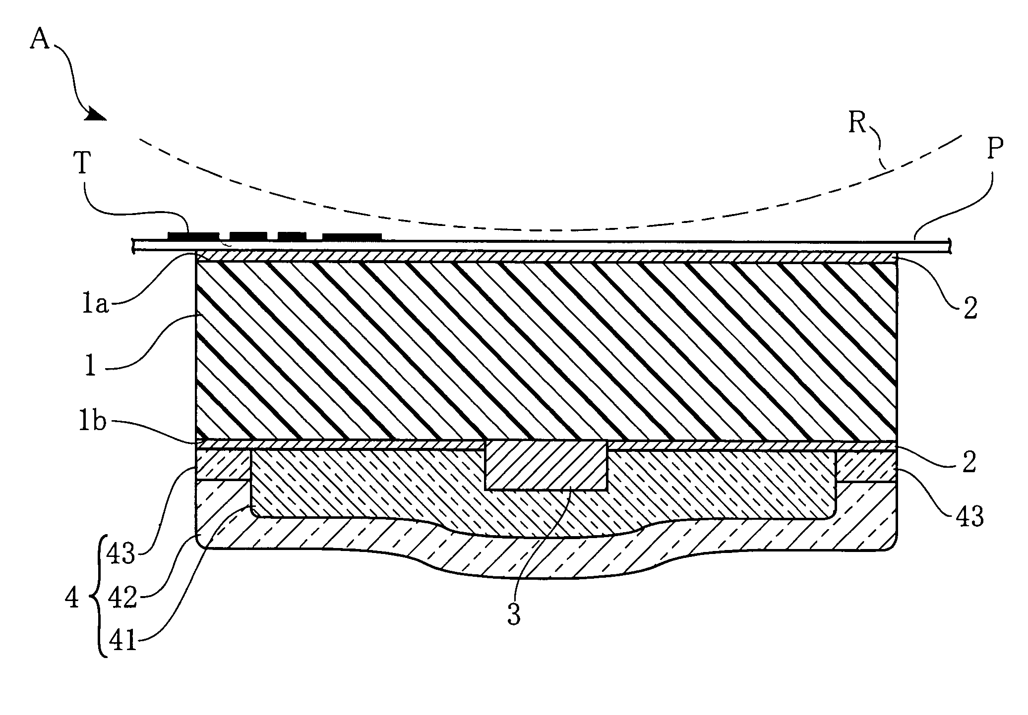
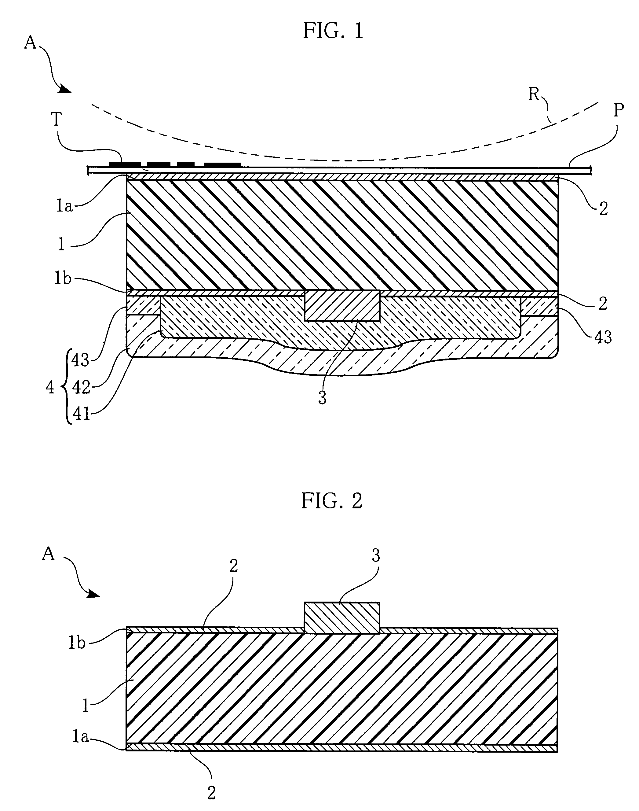
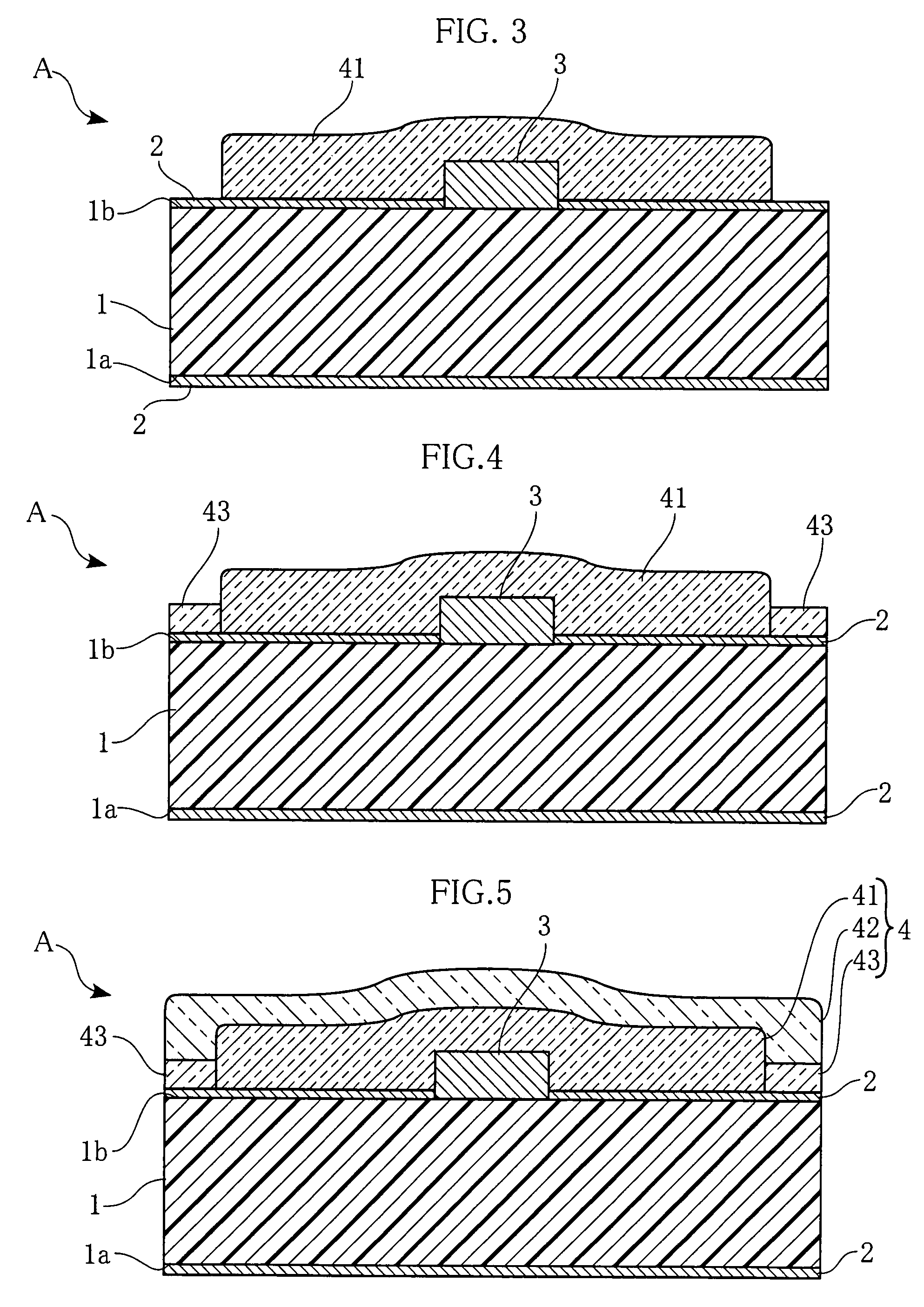
[0028]FIG. 1 is a cross-sectional view of a heating unit according to a first embodiment of the present invention. The illustrated heating unit A includes an AlN substrate 1, oxide layers 2, a heat-generating resistor 3, and a protection layer 4. The AlN substrate 1 has an upper or main surface 1a, and a lower or back surface 1b. The heating unit A is used in e.g. a printer to provide heat for fixing toner T on printing paper P. The printing paper P with the toner T transferred thereto is conveyed along the surface of the heating unit A under appropriate pressure provided by the pressure roller R, and the heat of the heating unit A fixes the toner T on the printing paper P.

[0029]The AlN substrate 1, made of aluminum nitride, is elongated in a direction perpendicular to the print paper conveying direction. The AlN substrate 1 is 7 to 14 mm in width and 0.5 to 0.7 mm in thickness. The aluminum nitride has excellent thermal response, and therefore the heat tends to spread substantially...


PUM


Abstract

A heating unit includes an AlN substrate having a main surface on which an elongated heat-generating resistor is provided. A protection layer is formed on the main surface of the substrate for the heat-generating resistor. The protection layer includes a first cover layer covering the heat-generating resistor and a second cover layer covering the first cover layer. The first cover layer is made of crystallized or semi-crystallized glass having a higher crystallization temperature by at least 50° C. than the softening point of the glass. The second cover layer is made of non-crystalline glass.

Description

BACKGROUND OF THE INVENTION[0001]1. Field of the Invention[0002]The present invention relates to a heating unit used in e.g. a printer for heating printing paper to thermally fix toner on the printing paper. In particular, it relates to a heating unit whose substrate is made of a ceramic material such as aluminum nitride (AlN). The present invention also relates to a method of making such a heating unit.[0003]2. Description of the Related Art[0004]For thermally fixing toner on the surface of a printing paper in a printing process, generally, a toner image formed on the surface of a photosensitive drum is transferred onto the printing paper, and then the printing paper is heated by a heating unit to fix the toner on the printing paper with the heat provided by the heating unit. Such fixing process is normally executed while conveying the printing paper under pressure through between the heating unit located on the side of the back surface of the printing paper and a pressure roller l...

Claims


Application Information

Patent Timeline
Patent Type & Authority Patents(United States)
IPC IPC(8): H05B3/26H05B3/28G03G15/20H01L23/31H01L23/29
CPCB41J2/3359
Inventor SAKO, TERUHISA
Owner ROHM CO LTD
Why Eureka
Try Eureka