Eureka AIR delivers breakthrough ideas for toughest innovation challenges, trusted by R&D personnel around the world.

Device for safeguarding an uninterruptible power supply of a magnet bearing in the event of failure of an electrical supply voltage

Active Publication Date: 2011-04-19
SIEMENS AG
View PDF16 Cites 3 Cited by
  • Summary
  • Abstract
  • Description
  • Claims
  • Application Information

AI Technical Summary

Benefits of technology

[0014]The invention is based on the object of avoiding damage to the bearings when using a magnet bearing during an interruption in the power supply of the magnet bearing in the event of failure of the electrical supply voltage.

Problems solved by technology

If the supply voltage of the magnet bearing fails, for example as a result of an electrical failure of the power supply system, not only will the motor run down, but also the functionality of the magnet bearing will no longer be provided.
However, applications of magnet bearings in fields with insufficiently stable electrical power supply systems are still problematic.
The maximum permissible number of emergency operation rundowns of the magnet bearing is then quickly reached, with the result that the abovementioned components need to be replaced even after a relatively short period of time.
This replacement is generally time-consuming and associated with high costs.
An uninterruptible power supply system maintains the functionality of the magnet bearing arrangement, for example of a shaft, until the rotating shaft is braked to a sufficient extent and no damage or wear occurs during mounting in the emergency bearing arrangement.
However, uninterruptible power supply systems have a plurality of disadvantages:Uninterruptible power supply systems represent a considerable cost factor in the case of magnet bearings.Uninterruptible power supply systems take up a considerable amount of physical space.In order to ensure the functionality of the batteries of an uninterruptible power supply system, certain environmental conditions such as temperature, air humidity etc. need to be adhered to.The batteries need to be tested and maintained regularly.

Method used


Image

  • Device for safeguarding an uninterruptible power supply of a magnet bearing in the event of failure of an electrical supply voltage
  • Device for safeguarding an uninterruptible power supply of a magnet bearing in the event of failure of an electrical supply voltage
  • Device for safeguarding an uninterruptible power supply of a magnet bearing in the event of failure of an electrical supply voltage

Examples


Embodiment Construction

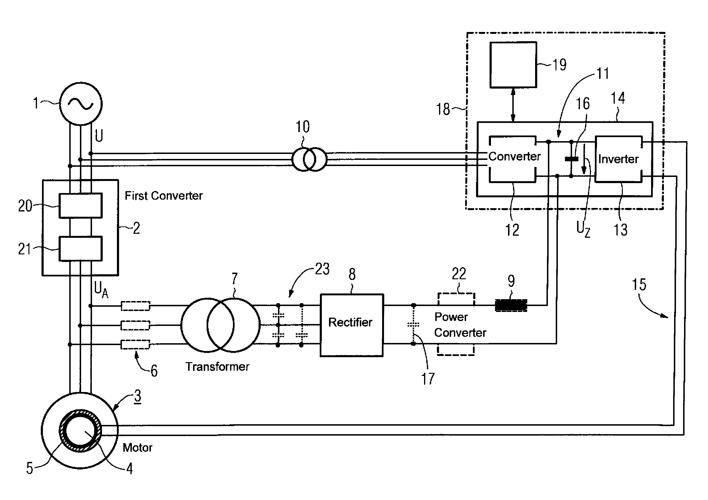
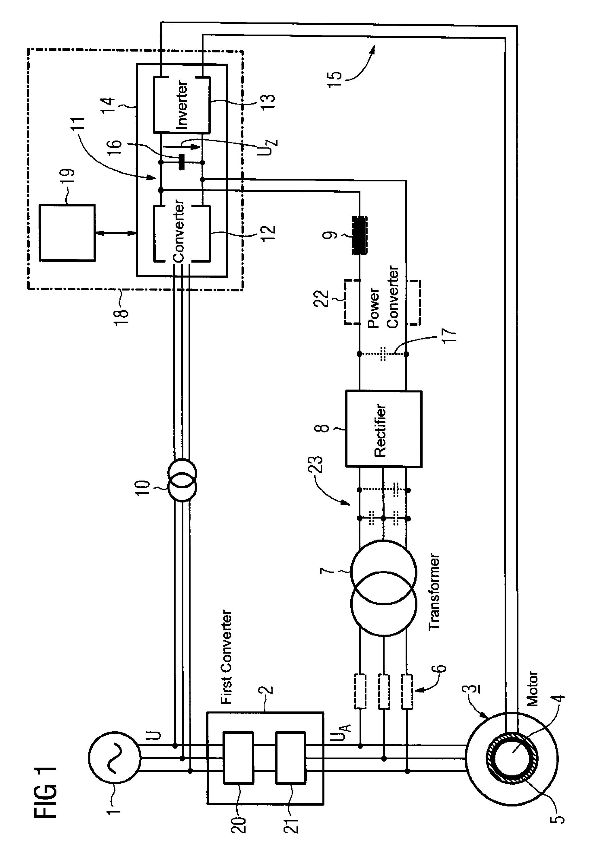
[0033]FIG. 1 shows a schematized electrical block circuit diagram of the device according to the invention. In this case, for reasons of clarity, only the components which are essential to the understanding of the invention are illustrated in FIG. 1; in particular only a drive unit 18 for driving the magnet bearing for one movement direction (for example X direction) is illustrated. A power supply system 1 is connected to a first converter 2 by means of a three-phase line, which is in turn connected to a motor 3 by means of a three-phase line. The motor 3 has a rotating shaft 4, which is mounted by means of a magnet bearing 5. The three-phase supply voltage U, which is made available by the power supply system 1, is rectified by the first converter 2 initially by means of a first power converter 20 and then inverted again by means of a second power converter 21 and the three-phase AC output voltage UA is generated. The motor 3 is thus driven by the first converter 2.

[0034]In the con...


PUM


Abstract

The invention relates to a device for safeguarding uninterrupted power supply of a magnetic bearing (5) in the event of a power supply voltage (U) failure. Said device comprises: a first frequency converter (2) which is supplied with power by the supply voltage (U) and controls a motor (3), and a transformer (7) which is connected to a rectifier (8) and the motor (3), said rectifier (8) supplying a DC-link electric circuit (11) of a second frequency converter (14) controlling the magnetic bearing (5) with power in the event of a power supply voltage failure. The invention allows prevention of damages to the magnetic bearing in the event of disruption of power supply of the magnetic bearing in the event of a power supply voltage failure.

Description

BACKGROUND OF THE INVENTION[0001]The invention relates to a device for safeguarding an uninterruptible power supply of a magnet bearing in the event of failure of an electrical supply voltage.[0002]The shafts of rapidly rotating motors are increasingly often mounted on contactless magnet bearings instead of conventional sliding or rolling bearings. A magnet bearing in this case always needs to be actively regulated.[0003]In motors, in particular in motors of machine tools, production machines and / or robots, magnet bearings are used to an increasing extent for bearing a motor shaft or any desired other shaft which is driven by a motor. Increasingly often magnet bearings are used in particular for bearing spindles.[0004]However, in contrast to conventional rolling body bearings, magnet bearings need to be continuously supplied with electrical energy in order to ensure a bearing arrangement in accordance with regulations. If the supply voltage of the magnet bearing fails, for example a...

Claims


Application Information

Patent Timeline
IPC IPC(8): H02K7/09F16C32/04H02J9/00H02P27/06
CPCF16C32/0442H02J9/066F16C32/0451F16C32/0457F16C2380/26
Inventor DENK, JOACHIMSTOIBER, DIETMARWEDEL, BERND
Owner SIEMENS AG
Why Eureka
Eureka Blog
Learn More