
Optical compensation film, polarizing plate, and liquid-crystal display device

a liquid crystal display device and optical compensation technology, applied in optics, instruments, optical elements, etc., can solve the problems of yellowish panel that should be white, unsatisfactory viewing angle characteristics of conventional pc display monitors, yellow color shift, etc., to improve the viewing angle characteristics of liquid crystal display devices and reduce yellow color shift

Inactive Publication Date: 2011-04-19
FUJIFILM CORP
View PDF3 Cites 2 Cited by
  • Summary
  • Abstract
  • Description
  • Claims
  • Application Information

AI Technical Summary

Benefits of technology

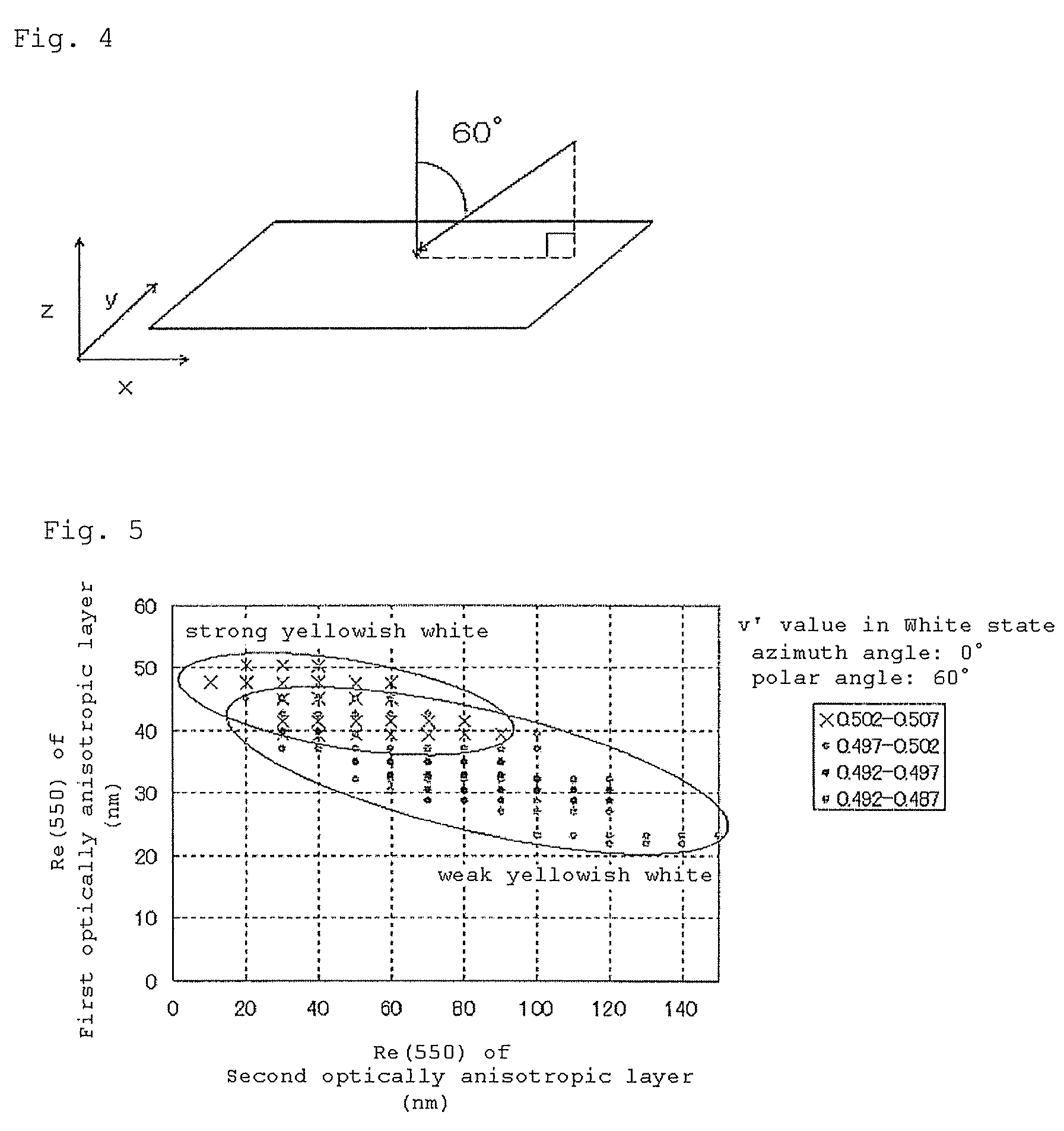
The invention provides a novel optical compensation film that can improve the viewing angle characteristics of liquid-crystal display devices, particularly reducing the yellow color shift that occurs in oblique horizontal directions in the white state. The film has specific retardation values in its first and second layers, and can be used in combination with a polarizing plate and a liquid-crystal display device to enhance the viewing angle. The technical effects of the invention include improved color accuracy and reduced yellow color shift in liquid-crystal display devices.

Problems solved by technology

However, in the embodiments where the conventional optical compensation film having the above described constitution is actually used in a TN-mode liquid-crystal display device, and when the device is watched in oblique horizontal directions in the white state, then the panel that should be white may often look yellowish.
In particular, in many cases, the display panel of TVs and TV function-having PCs may be watched by plural viewers in various directions; and the viewing angle characteristics satisfactory for conventional PC display monitors are not satisfactory for TVs (or display monitors of TV function-having PCs).

Method used


Image

  • Optical compensation film, polarizing plate, and liquid-crystal display device
  • Optical compensation film, polarizing plate, and liquid-crystal display device
  • Optical compensation film, polarizing plate, and liquid-crystal display device

Examples


example 1

(Formation of Second Optically-Anisotropic Layer (Cellulose Acylate Film 1))

[0303]The ingredients shown in the following Table were mixed to prepare a cellulose acylate solution. The cellulose acylate solution was cast on a metal support, and the formed web was peeled away from the support, and stretched in TD direction by 20% at 185° C. to produce a cellulose acylate film 1. TD direction means the direction perpendicular to the film traveling direction. After stretched, the thickness of the film was 80 μm.

[0304]

IngredientCellulose acylate having a degree of acetyl substitution of 2.94100 mas. pts.Triphenyl phosphate 3 mas. pts.Biphenyl phosphate 2 mas. pts.Retardation-controlling agent (1) 5 mas. pts.Retardation-controlling agent (2) 2 mas. pts.Methylene chloride644 mas. pts.Methanol 56 mas. pts.Retardation-Controlling Agent (1):Retardation-Controlling Agent (2):

[0305]Re(550) of the cellulose acylate film 1 obtained in the above was 80 nm, and Rth(550) thereof was 60 nm.

(Formation ...

example 2

(Formation of Second Optically-Anisotropic Layer (Cellulose Acylate Film 2))

[0320]A cellulose acylate film (TAC-TD80U, by FUJIFILM) was stretched in TD direction by 20% at 240° C. to prepare Cellulose acylate film 2. The thickness of the stretched film was 80 μm.

[0321]Re(550) of Cellulose acylate film 2 was 60 nm, and Re(550) thereof was 60 nm.

[0322]In the same manner as in Example 1, an alignment film and a first optically-anisotropic layer were formed, thereby fabricating Optical compensation film 2 and Polarizing plate 2; and using Polarizing plate 2 and in the same manner as in Example 1, TN-mode liquid-crystal display device 2 was constructed.

example 3

[0340]An optical compensation film, a polarizing plate and a TN-mode liquid-crystal display device were produced in the same manner as in Example 1, for which, however, a cyclic polyolefin film produced according to the method described below was used as the second optically-anisotropic layer (Re(550)=80 nm, Rth(550)=60 nm). The test results of the device were also excellent like those of TN-mode liquid-crystal display device 1 produced in Example 1.

(Preparation of Ring-Opening Polymerized Cyclic Polyolefin)

[0341]The following composition was put into a mixing tank and stirred to dissolve the ingredients, and then the solution was filtered through a filter paper having a mean pore size of 34 μm and a sintered metal filer having a mean pore size of 10 μm.

[0342]

Cyclic Polyolefin Solution AArton G (by JSR)150mas. pts.Methylene chloride550mas. pts.Ethanol50mas. pts.

[0343]Next, the following composition containing the ring-opening polymerized cyclic polyolefin solution prepared according...


PUM

PropertyMeasurementUnit
wavelengthaaaaaaaaaa

Abstract

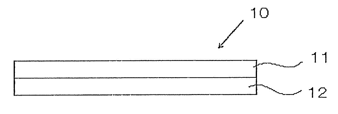
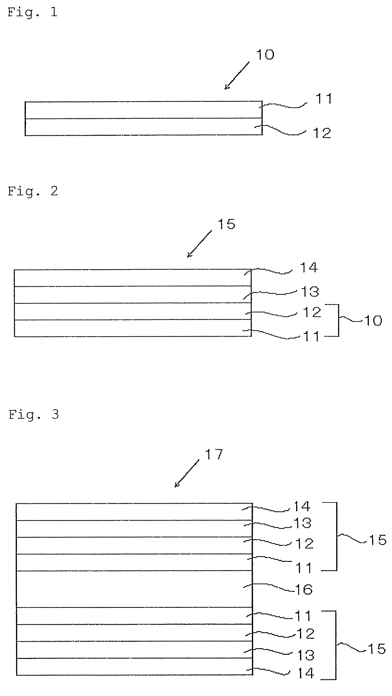
Disclosed is an optical compensation film comprising first and second optically-anisotropic layers, wherein retardation in plane at a wavelength of 550 nm, Re(550), of the first optically-anisotropic layer is from 20 to 40 nm, the first optically-anisotropic layer does not have any direction in which its retardation at a wavelength of 550 nm is 0 nm, the direction in which the absolute value of retardation of the first optically-anisotropic layer is the smallest is neither in the normal line direction of the layer nor in the in-plane direction thereof, and Re(550) of the second optically-anisotropic layer is from 20 to 150 nm and retardation along thickness direction at a wavelength of 550 nm, Rth(550), thereof is from 40 to 110 nm.

Description

CROSS-REFERENCE TO RELATED APPLICATIONS[0001]This application claims benefit of priority under 35 U.S.C. 119 to Japanese Patent Application Nos. 2007-251748 filed on Sep. 27, 2007, and 2008-230530 filed on Sep. 9, 2008; and the entire contents of the application are incorporated herein by reference.BACKGROUND OF THE INVENTION[0002]1. Field of the Invention[0003]The present invention relates to an optical compensation film and a liquid-crystal display device, and in particular, to an optical compensation film useful for optical compensation of TN-mode liquid-crystal display devices, and to a TN-mode liquid-crystal display device comprising it.[0004]2. Related Art[0005]Heretofore, various optical compensation films having, on a transparent support, an optically-anisotropic layer formed of a liquid-crystal composition have been proposed for optical compensation films of TN-mode liquid-crystal display devices. The optical compensation film having such a constitution is generally so desi...

Claims


Application Information

Patent Timeline
Patent Type & Authority Patents(United States)
IPC IPC(8): G02F1/1335
CPCG02B5/3083G02F1/133632G02F2413/105G02F2001/133633G02F1/133633
Inventor SATO, HIROSHIICHINOSE, TOMONORI
Owner FUJIFILM CORP
Learn More