
Systems and methods for distributing a workplan for data flow execution based on an arbitrary graph describing the desired data flow

a data flow and workplan technology, applied in the field of database systems, can solve the problems of complex transformations that require custom development of new etl tools with specific and complex functionality, complex etl tools that do not lend themselves to reusability, and high resource consumption, so as to improve connection performance, improve the efficiency and aggressive utilization of resources of the machine running the pipeline, and improve the effect of connection performan

Active Publication Date: 2011-04-19
MICROSOFT TECH LICENSING LLC
View PDF31 Cites 21 Cited by
  • Summary
  • Abstract
  • Description
  • Claims
  • Application Information

AI Technical Summary

Benefits of technology

This approach enhances the scalability and performance of data flow handling systems by allowing concurrent processing across multiple processors, increasing runtime performance proportionally with the number of available processors, and optimizing resource utilization.

Problems solved by technology

However, while basic transformations can be achieved with simple ETL tools, complex transformations require custom development of new ETL tools with specific and complex functionality—an approach that is resource intensive.
While simple ETL tools might have broader usability and thus naturally lend themselves to widespread reuse, complex ETL tools do not lend themselves to reusability due to their high customization and narrow utility (and thus the frequent need to custom develop complex ETL tools when they are needed).

Method used


Image

  • Systems and methods for distributing a workplan for data flow execution based on an arbitrary graph describing the desired data flow
  • Systems and methods for distributing a workplan for data flow execution based on an arbitrary graph describing the desired data flow
  • Systems and methods for distributing a workplan for data flow execution based on an arbitrary graph describing the desired data flow

Examples


Embodiment Construction

Overview

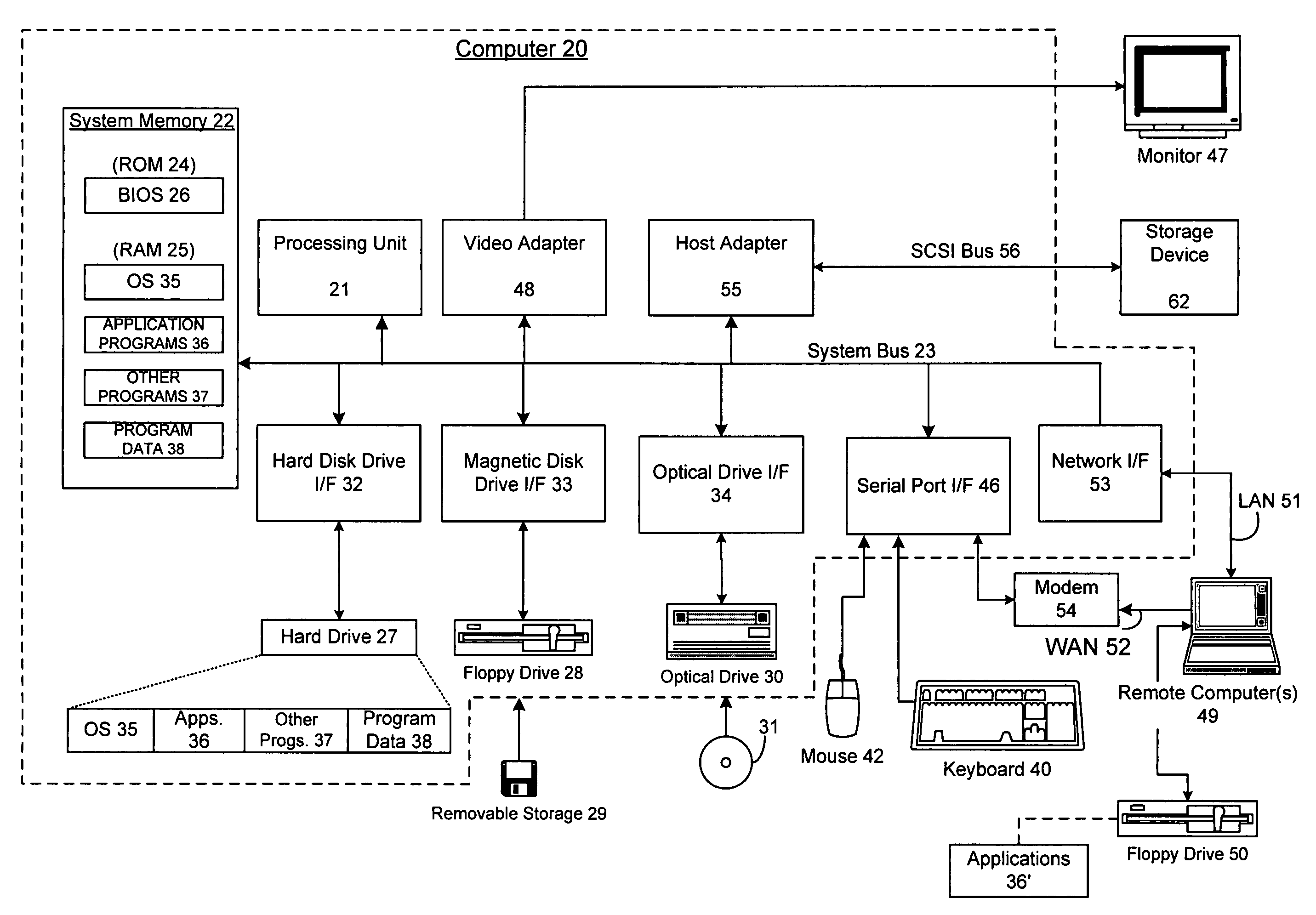
[0038]The following discussion is directed to systems and methods for distributing work of a data flow engine across multiple processors to improve performance in connection with data flow handling systems. The subject matter is described with specificity to meet statutory requirements. However, the description itself is not intended to limit the scope of this patent. Rather, the inventors have contemplated that the claimed subject matter might also be embodied in other ways, to include different elements or combinations of elements similar to the ones described in this document, in conjunction with other present or future technologies. Moreover, where the embodiments described herein describe the invention in connection with row-level access and processing, it should be noted that the invention is by no means limited to row-level access and processing and could be applied on a column basis or a table basis as well.

Computer Environment

[0039]FIG. 1 and the following discussio...


PUM


Abstract

Various embodiments of the present invention are directed to the creation of multiple redundant chains of transforms, each on a separate processing thread, for a data flow execution (DFE) of a data transformation pipeline (DTP). For certain of these embodiments, a “distributor” receives a buffer as input and directs that buffer to one of several parallel identical threads to process that buffer. A scheduler would create each of these multiple threads, each thread having an identical (redundant) strings of transforms (chains) downstream from the distributor, and all of which would lead even further downstream to a collector that is responsible for collecting and, if necessary, ordering the buffers processed by the previous redundant chains. In this way, the distributors and collectors provide increased scalability for the pipeline by implicitly partitioning (distributing) individual buffers to one of many threads for at least a part of their execution / processing.

Description

CROSS-RELATED APPLICATIONS[0001]This application claims benefit of U.S. Provisional Application No. 60 / 573,963, entitled “SYSTEMS AND METHODS FOR DISTRIBUTING A WORKPLAN FOR DATA FLOW EXECUTION BASED ON AN ARBITRARY GRAPH DESCRIBING THE DESIRED DATA FLOW”, filed May 24, 2004, the entire contents of which are hereby incorporated herein by reference.[0002]This application is also related to the following commonly-assigned patent applications, the entire contents of each are hereby incorporated herein this present application by reference: U.S. patent application Ser. No. 10 / 681,610, entitled “SYSTEMS AND METHODS FOR TRANSFORMING DATA IN BUFFER MEMORY WITHOUT UNNECESSARILY COPYING DATA TO ADDITIONAL MEMORY LOCATIONS”, filed Oct. 8, 2003; which is a continuation-in-part of U.S. patent application Ser. No. 10 / 391,726, entitled “SYSTEMS AND METHODS FOR SCHEDULING DATA FLOW EXECUTION BASED ON AN ARBITRARY GRAPH DESCRIBING THE DESIRED DATA FLOW”, filed Mar. 18, 2003.FIELD OF THE INVENTION[0...

Claims


Application Information

Patent Timeline
Patent Type & Authority Patents(United States)
IPC IPC(8): G06F15/16G06F7/00G06F17/50
CPCG06F17/30592G06F17/30563G06F16/254G06F16/283
Inventor BLASZCZAK, MICHAEL A.
Owner MICROSOFT TECH LICENSING LLC
Learn More