Nozzle for use in connection with dosing of a material from a container, method and use thereof

a technology for dosing nozzles and containers, which is applied in the direction of liquid dispensing, containers, pliable tubular containers, etc., can solve the problems of reducing affecting the quality of work, and affecting the work efficiency of workers, so as to achieve the effect of being cheap to produ

Inactive Publication Date: 2011-04-26
CLAUS LEONHARDT JENSEN & FINN HOLME HJORT
View PDF10 Cites 14 Cited by
  • Summary
  • Abstract
  • Description
  • Claims
  • Application Information

AI Technical Summary

Benefits of technology

[0011]The invention is a nozzle which is not encumbered with the problems which are described above in connection with the known nozzles within the field, and which is inexpensive to produce. Furthermore, a nozzle in accordance with the invention is flexible and good to use, and at the same time one that it is durable regardless of the kind of treatment to which it is exposed.
[0017]It is also possible to have one or more extra parts which can be slid in between a nozzle base and a nozzle tip. The part or parts will be able to be connected respectively to the nozzle base and the nozzle tip (and possibly each other with further extra parts) by means of a swivel link. The extra parts will possible require further locking mechanisms in order to lock all of the parts to each other, but at the same time will increase the flexibility of the nozzle.
[0030]With a further aspect of the invention, the surfaces are circular and one of the surfaces along the edge is provided with a collar which grips over the second surface. It is hereby possible to connect the nozzle parts to each other in a manner which is simple and cheap to produce. This is because the production tolerances on the collar and the surfaces are less critical, merely providing that the collar grips in over the second surface. In connection with the use of the nozzle, the second surface will be pressed out against the collar, whereby a tight closing of the link is established.
[0032]In an alternative embodiment, the link can be created by a protruding part on, for example, the nozzle base, which enters into engagement with a recess in the opposite part, for example, the nozzle tip. In order for the nozzle to function, it will be required that the protruding part has a through-going channel where the material which shall be applied with the nozzle can be fed. With this embodiment of the link, it is possible to create a link which is quick and simple to assemble, but where the production tolerances on the protruding part and recess are important in ensuring that the link doe not separate during use or become leaky.
[0035]The raised parts or the recesses can have any configuration whatever, but if these have a substantially triangular or square cross-section towards the bolt, it will be ensured that the bolt is not pressed up over or out of a raised part / recess. At the same time, the collar with the raised parts or recesses will be easy to produce.
[0037]With a still further aspect of the invention, the locking mechanism comprises at least one bolt which is slid in over one of the raised parts or into recesses in the link. It is hereby possible to have a locking mechanism placed on the side of the nozzle, and slide it sideways in over the raised parts or alternatively into the recesses. With the sideways movement of the locking mechanism, it will be easier to operate the locking mechanism under conditions where, for example, work gloves are worn, than with a pivotal locking mechanism with a part which has to be lifted or swiveled around an axle. Also, it is less likely that the locking mechanism will be jammed or blocked by the sideways movement, and it will be easier to exert extra strength to create a movement.

Problems solved by technology

An important problem in connection with standard containers with nozzles is that the nozzles have a firm conical tube of a certain length, where this considerably limits the working positions which can be assumed by a person using the container.
The alternative for the person will often be to twist the body in an unhealthy working position, such as working with the jointing gun raised high above the head.
The result will often be a less effective execution of the work or a poor quality of work.
In the long run, bad working positions will presumably also result in aching muscles and eventual industrial injury.
However, nozzles of this type have not gained great application, the reason being that their flexible tips have not proved useful, particularly on building sites where the work tempo is high and the work tools are handled in a correspondingly hard manner.
The flexible tips have not been able to tolerate this treatment, whereby the advantageous working angle or the whole of the nozzle has been ruined.

Method used


Image

  • Nozzle for use in connection with dosing of a material from a container, method and use thereof
  • Nozzle for use in connection with dosing of a material from a container, method and use thereof
  • Nozzle for use in connection with dosing of a material from a container, method and use thereof

Examples


first embodiment

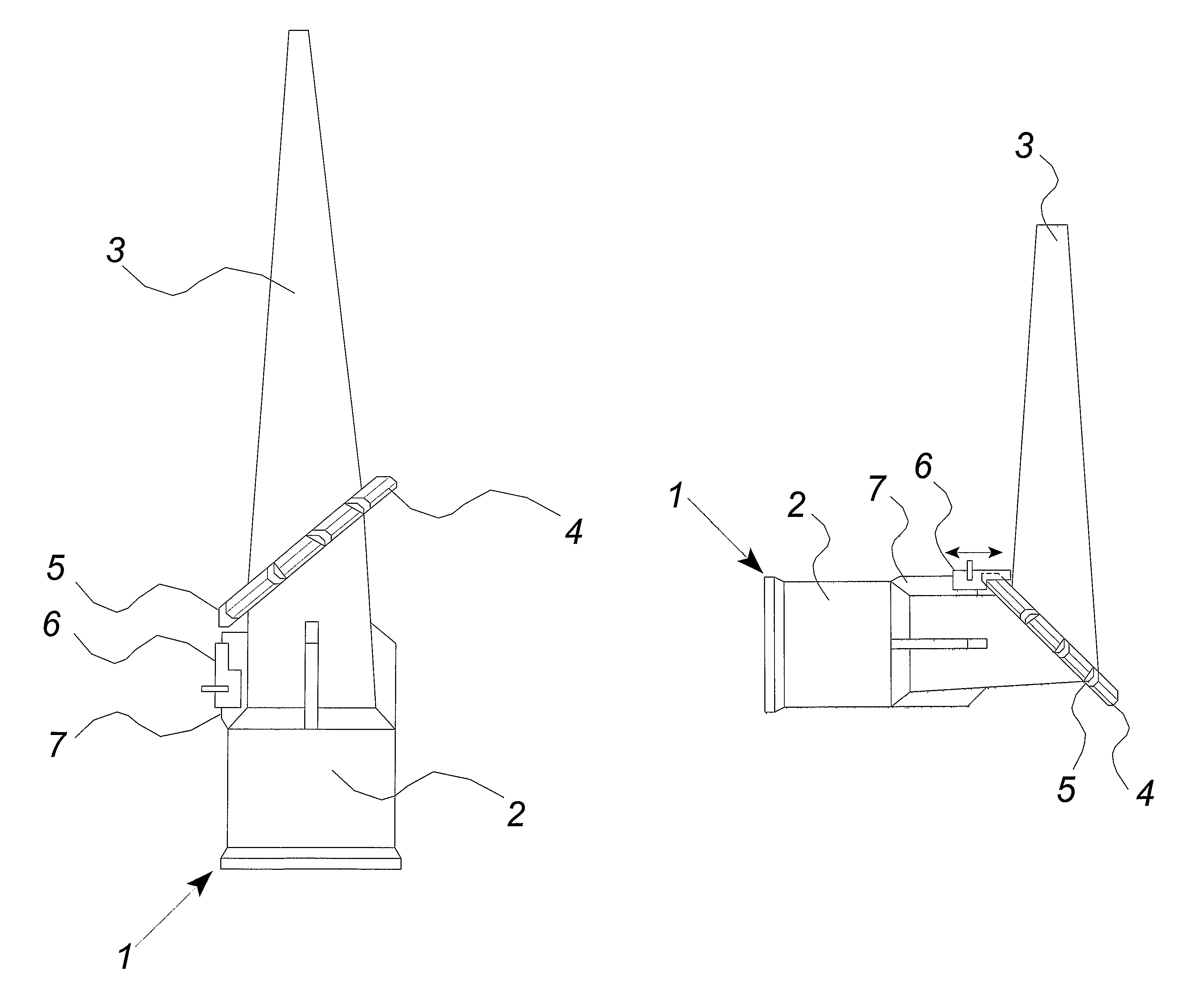
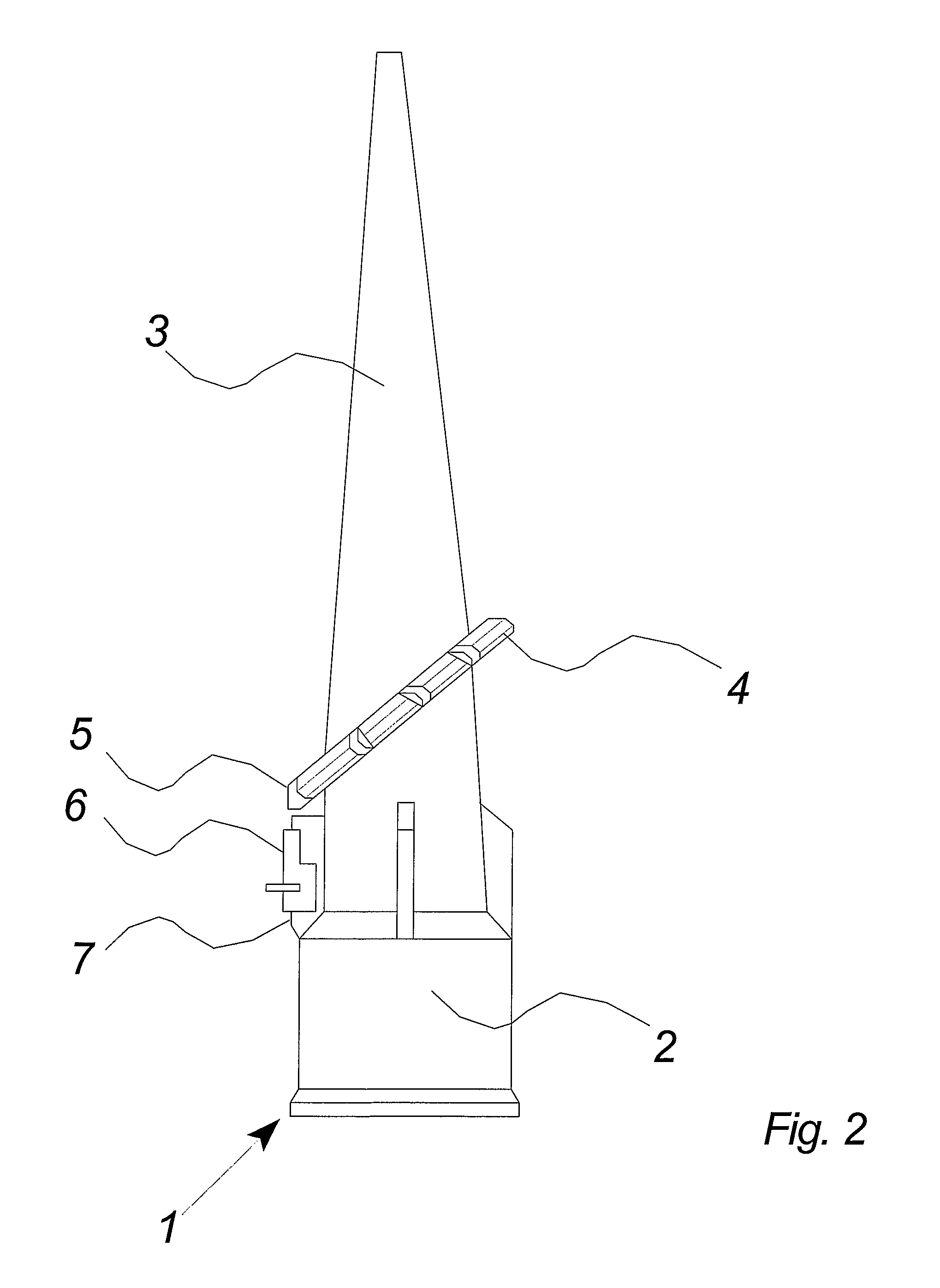
[0056]FIGS. 2-7 show a nozzle 1 according to the invention.

[0057]FIG. 2 shows the nozzle 1 which is made up of two main parts, a nozzle base 2 and a nozzle tip 3, where these are connected to each other via a circular swivel link 4. The swivel link is provided with a number of raised parts 5 which are distributed evenly along the edge of the swivel link.

[0058]The nozzle base is provided with a bolt 6 which can be displaced on a slide rail 7 from an unlocked to a locked position, where the bolt in the locked position enters into engagement with one of the raised parts in the swivel link.

[0059]In the drawing, the bolt 6 is shown in its unlocked position, where the nozzle tip can be turned to a desired angle in relation to the nozzle base and the longitudinal axis of the nozzle.

[0060]FIG. 3 shows the nozzle in a situation, where the nozzle tip 3 has been turned into a desired angle in relation to the nozzle base and the longitudinal axis of the nozzle. After the turning, the bolt 6 is ...


PUM


Abstract

A nozzle (1) is disclosed for use in connection with the providing of a fluid material from a container, where the nozzle comprises a first nozzle base part (2), a nozzle tip part and a link (4) connecting the nozzle parts (2, 3). The link (4) has a first pivotal state and a second locked state when the link is under pressure by the material flow The link (4) has a first surface (8) and second surface (10), the surfaces being pivotally connected to each other, and where said surfaces (8, 10) are angled in relation to the longitudinal center axis of the nozzle. The invention also relates to a use of the nozzle (1).

Description

BACKGROUND OF THE INVENTION[0001]1. Field of the Invention[0002]The invention relates to a nozzle for use in connection with dosing of a material from a container.[0003]A use for a nozzle of the above-mentioned kind is in connection with a container such as a cartridge or tube containing filler, silicone, glue or similar materials. The nozzle is the opening for the container and, in connection with the emptying of the container, shall among other things ensure that a suitable amount of the material in the container can be applied in a desired place. The cartridge or the tube often has a built-in nozzle, or is supplied together with the nozzle, which can subsequently be mounted over an opening in the cartridge or the tube.[0004]2. Description of the Prior Art[0005]A cartridge with for example glue, filler or silicone material will often be placed in a caulking or jointing gun, which ensures that the material can easily be pressed out of the cartridge in a uniform stream. A tube or ot...

Claims


Application Information

Patent Timeline
Patent Type & Authority Patents(United States)
IPC IPC(8): B65D5/72
CPCB05C17/00516B05C17/00596
Inventor HJORT, FINN HOLME
Owner CLAUS LEONHARDT JENSEN & FINN HOLME HJORT
Why Eureka
Try Eureka