Shaped ground plane for radio apparatus

a radio apparatus and ground plane technology, applied in the structural form of antennas, radiating elements, antenna supports/mountings, etc., can solve the problems of inconvenient and uncomfortable carrying of phones inside pockets and extracting difficult to pack resonant antennas into space which is small in terms of wavelength at resonance, and inconvenient to carry phones inside pockets and to extract them outside for operation, etc., to achieve a high degree of miniaturization, enhance the miniaturization

Active Publication Date: 2011-04-26
FRACTUS
View PDF59 Cites 30 Cited by
  • Summary
  • Abstract
  • Description
  • Claims
  • Application Information

AI Technical Summary

Benefits of technology

[0012]The object of the present invention is, therefore, to provide an antenna structure, a wireless device and a method to integrate an antenna structure which allows for a reduced size of the wireless devices with respect to known wireless devices.
[0121]In addition to their multiband behavior, multilevel structure ground plane may have a smaller than usual size as compared to other ground plane of a simpler structure (such as those consisting of a single polygon or polyhedron). Additionally, the edge-rich and discontinuity-rich structure of a multilevel ground plane may enhance the radiation process, relatively increasing the radiation resistance of the ground plane and reducing the quality factor Q ,i.e. increasing its bandwidth.

Problems solved by technology

External antennas feature several drawbacks: they can break accidentally under mechanical stress or shock and they make the phone more inconvenient and uncomfortable to carry inside a pocket and to extract it outside for operation.
The desire to make smaller, thinner phones may conflict with the trend of adding more features to the phone.
It also means that is difficult to pack a resonant antenna into a space which is small in terms of the wavelength at resonance.
Other characteristics of a small antenna are its small radiating resistance and its low efficiency.
One of the drawbacks of this is that having the antenna on one side of the PCB and other components on the back side of such a PCB implies a minimum thickness for the whole handset device.
It is well known that the performance of such antennas is limited, in terms of bandwidth, efficiency and related parameters (gain, VSWR and so on) by the spacing between said conducting element and the ground layer: the shorter the distance between both, the smaller the bandwidth and efficiency.
For the typical 5-15% bandwidths of a cellular / mobile system (GSM, UMTS, PCS, WCDMA), the minimum distance is about 2% of the longest operating wavelength (typical 7-9 mm), which again introduces a significant limitation in the development of thin, slim phones with multiple-band or wide-band operation.

Method used


Image

  • Shaped ground plane for radio apparatus
  • Shaped ground plane for radio apparatus
  • Shaped ground plane for radio apparatus

Examples


example embodiments

DESCRIPTION OF EXAMPLE EMBODIMENTS

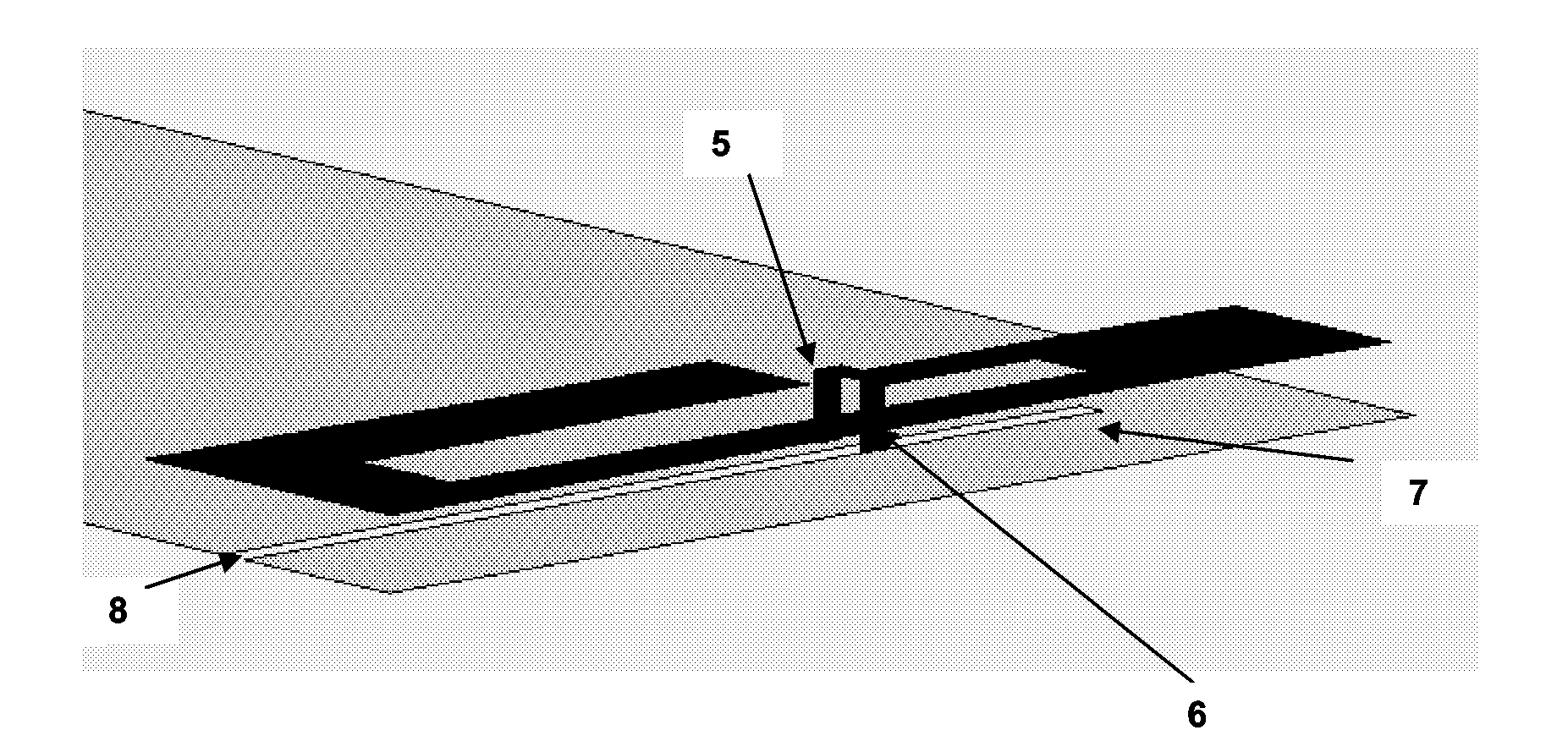
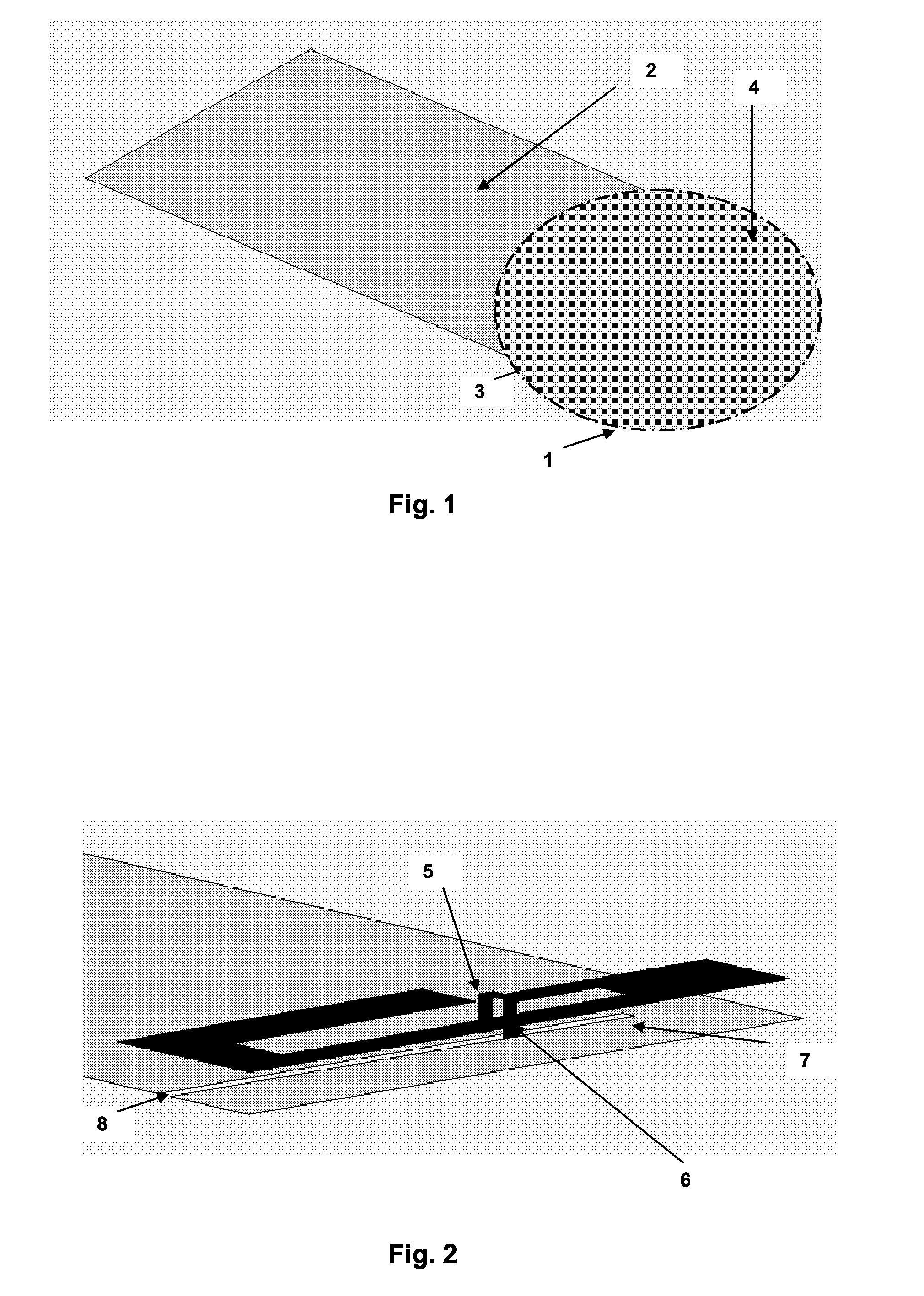
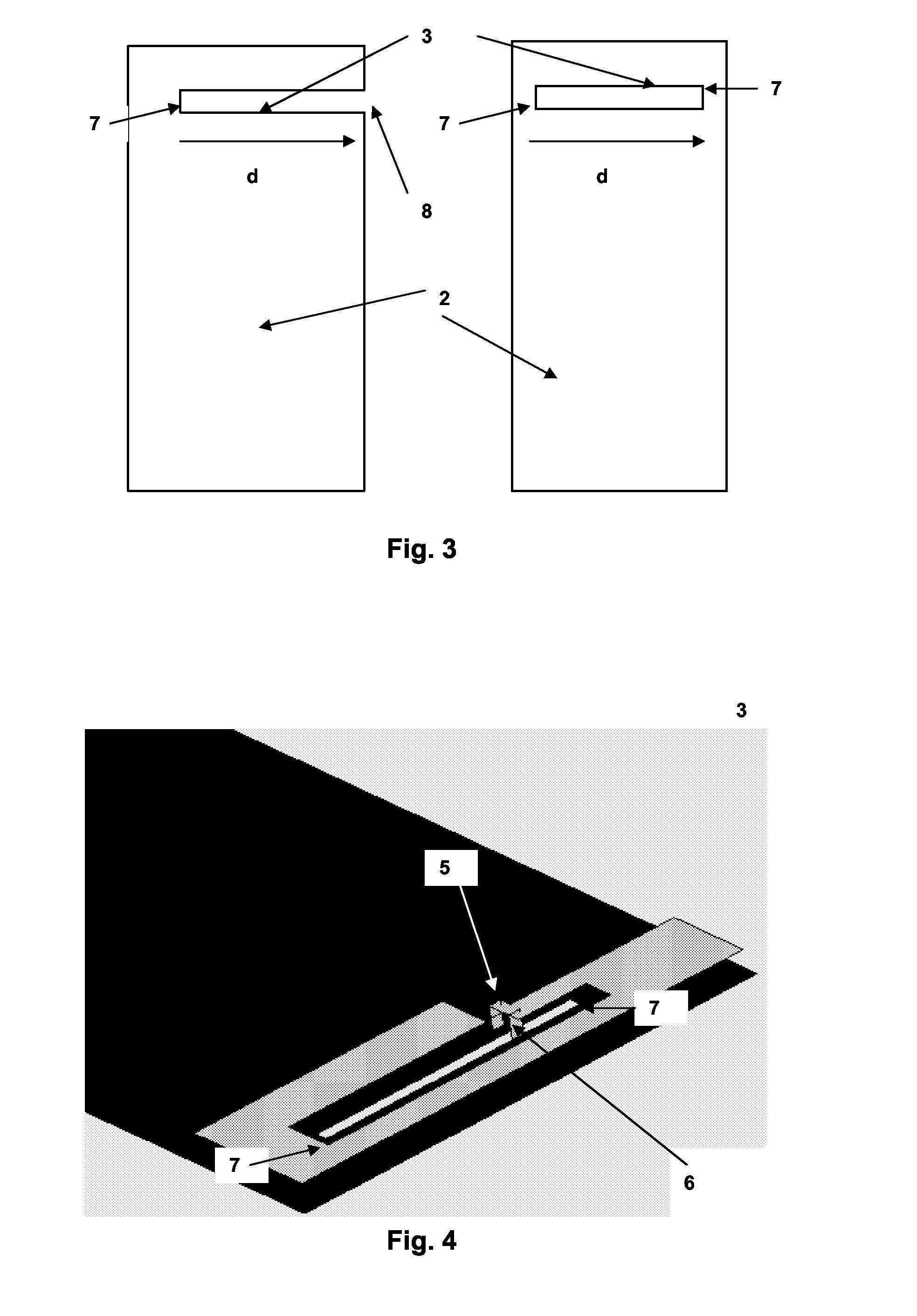
[0140]FIGS. 1-10, illustrate examples of an antenna structure for a wireless device, comprising a slotted ground plane 2 comprising at least one slot 3 and an antenna element 4 with at least one feeding 5 and one ground 6 connection.

[0141]FIG. 1 shows an example of an antenna element 4 and a slotted ground plane 2. The conducting ground plane 2, is typically embedded on the PCB of a wireless device. A straight slot 3 on the ground plane 2 features an open end 8 and a short end 7. An antenna element 4 is placed over the ground plane 2. Such an antenna element 4 features a substantially planar conducting surface with two substantially vertical connections. In this example, both connections are substantially close to the short end 7 of the slot 3. In particular the distance to the short end 7 is smaller than half of the length of the slot 3 about ⅓rd the length of the slot 3. As a result the set 1 of antenna element 4 and the slotted ground plane 2 rad...


PUM


Abstract

This invention refers to an antenna structure for a wireless device comprising a ground plane and an antenna element, wherein the ground plane has a slot with at least a short end, an open end and a length substantially close to a quarter wavelength. The feeding and ground connections of the antenna structure are placed at the two different sides of said slot and the distance of at least one of them to the short end of the slot is equal or smaller than an eighth of the wavelength. The invention further refers to an antenna structure for a wireless device comprising a ground plane and an antenna element, wherein the ground plane has a slot with at least two short ends, and a length substantially close to half wavelength. The feeding and ground connections of the antenna structure are placed at the two different sides of said slot and the distance of at least one of them to a short end of the slot is equal or smaller than a quarter of the wavelength. Further the invention refers to a corresponding wireless device, a corresponding mobile phone and to a method for integrating such an antenna structure within a wireless device.

Description

CROSS-REFERENCE TO RELATED APPLICATIONS[0001]This patent application claims the benefit of priority from U.S. Provisional Patent Application No. 60 / 640,645 filed Dec. 30, 2004. This application incorporates by reference the entire disclosure of U.S. Provisional Patent Application No. 60 / 640,645.[0002]This application is related to application number U.S. 60 / 640,645 filed on Dec. 30, 2004, in the U.S. and claims priority to that application, which is incorporated herein by reference.[0003]The present invention refers to an antenna structure for a wireless device which comprises a ground plane and an antenna element. Further the invention refers to a wireless device with such an antenna structure and to a method for integrating such an antenna structure within a wireless device. The invention relates to a radio frequency (RF) ground plane used in combination with an antenna element placed inside a radio apparatus.BACKGROUND OF THE INVENTION[0004]In many applications, such as for insta...

Claims


Application Information

Patent Timeline
Patent Type & Authority Patents(United States)
IPC IPC(8): H01Q1/24
CPCH01Q1/243H01Q9/0421H01Q1/48H01Q1/36
Inventor PROS, JAUME ANGUERABALIARDA, CARLES PUENTE
Owner FRACTUS
Why Eureka
Try Eureka