Method and tool for determination of fracture geometry in subterranean formations based on in-situ neutron activation analysis

a technology of neutron activation analysis and fracture geometry, which is applied in the direction of survey, instruments, borehole/well accessories, etc., can solve the problems of adding operation costs, wasting materials used to maintain fractures after fluid pressure reduction, and expensive to efficiently operate wells

Active Publication Date: 2011-04-26
HEXION INC
View PDF31 Cites 27 Cited by
  • Summary
  • Abstract
  • Description
  • Claims
  • Application Information

AI Technical Summary

Benefits of technology

[0014]The present invention solves the existing problems in the art by providing a method for analyzing the results of a fracturing process by collecting and analyzing well logging data, comprising disposing in a formation fracture, a proppant and / or a fracturing fluid that comprises a radiation susceptible material; during a single logging pass irradiating the radiation susceptible material with neutrons; measuring gamma-radiation emitted from the radiation susceptible material; and processing the measured gamma-radiation data in accordance with a Monte Carlo-based simulation model to obtain an estimated fracture geometry (e.g. propped height and / or propped fracture width near the wellbore).

Problems solved by technology

Addressing the problems arising from an out-of-zone fracture will also add expenses to the operation.
In addition, if the fracture propagates into an adjacent non-hydrocarbon producing formation, the materials used to maintain a fracture after the fluid pressure has decreased may be wasted in areas outside the productive formation area.
In short, it is expensive to efficiently operate a well that has been fractured out of the hydrocarbon-producing zone.
However, this technique is subject to limitations and ambiguities.
For example, the temperature log may be difficult to interpret because of low temperature contrast, flowback from the formation before and after the treatment, or fluid movement behind the borehole casing.
In addition, the use of radioactive tracers may give rise to environmental problems such as the pollution of underground water streams, and the like, and hence be undesirable.
Utilizing a borehole televiewer is limited in that it can only be used for fracture height evaluation in open holes.
In addition, utilizing a borehole televiewer is limited due to the extreme temperature and pressure conditions present in deeper completions.
Acoustical methods are hampered by inhomogeneous formation impedance and / or the need for pumping while the tool is in the wellbore.
In addition to the problems associated with each type of known monitoring method, there are inherent problems in the formation fracturing technology.
One problem with the existing technology is that the methods for determining whether a formation has been fractured out of the production zone relies on post-treatment (i.e. after the fracture has occurred) measurements.
Moreover, with existing detection systems, the wait for post-fracturing data can take a considerable amount of time, even up to several days, which can delay the completion operations, resulting in higher completion and operating costs.
Another problem associated with existing post-process “logging” or measuring devices is that the cost associated with interrupting a fracturing job in order to make a measurement of a fracture is neither practical nor feasible.
Because the fracturing fluid is pumped into a formation under high pressures during the fracturing process, temporarily halting the pumping during the fracturing operation will result in the application of pressure to the fracturing fluid by the walls of the formation fracture.
This could lead to undesirable results such as the closing of the fractures, thereby causing the reversal of fluid flow back into the borehole, or the build-up of sand in the hole.
In addition, after taking measurements and completing the logging process, operators cannot restart the pumping equipment at the point of the fracturing process immediately before the interruption.
Instead, the operators would have to repeat the complete fracturing job at additional cost and with unpredictable results.

Method used


Image

  • Method and tool for determination of fracture geometry in subterranean formations based on in-situ neutron activation analysis
  • Method and tool for determination of fracture geometry in subterranean formations based on in-situ neutron activation analysis
  • Method and tool for determination of fracture geometry in subterranean formations based on in-situ neutron activation analysis

Examples


Embodiment Construction

yzing measured neutron activation data from a well fracture in accordance with an embodiment of the present invention; and

[0020]FIG. 4 depicts a cross-sectional view of a three-dimensional input to a neutron transport calculation model in accordance with the method of the present invention.

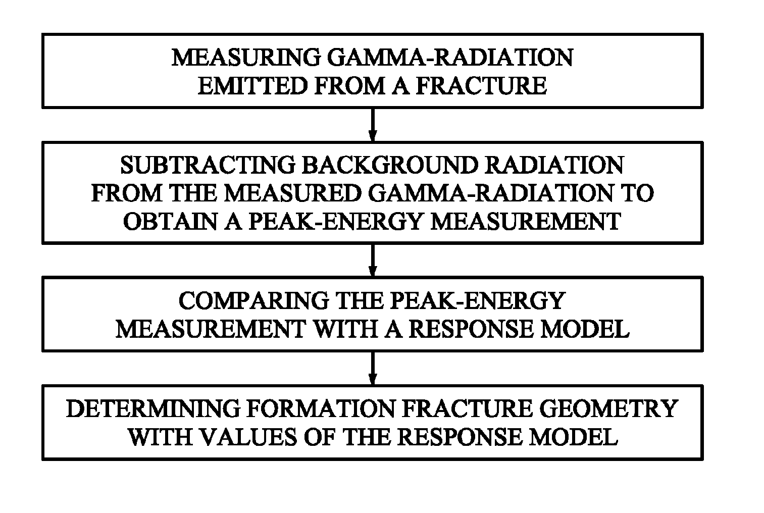
[0021]FIG. 5 depicts a flow chart scheme of one embodiment of a method of determining fracture geometry of a subterranean formation from radiation emitted from a fracture in said formation.

[0022]FIG. 6 depicts a flow chart scheme of one embodiment of a method for modeling geometrical parameters of a subterranean formation fracture detected by collecting gamma-radiation data stimulated by a neutron source.

DETAILED DESCRIPTION OF THE INVENTION

[0023]In accordance with the present invention, a method for determining fracture geometry uses environmentally friendly materials. These environmentally friendly materials are nonradioactive until bombarded by neutrons and will be referred to as radiation susc...


PUM


Abstract

A method for determining fracture geometry of a subterranean formation from radiation emitted from a fracture in the formation, including measuring gamma-radiation emitted from the fracture; subtracting background radiation from the measured gamma-radiation to obtain a peak-energy measurement; comparing the peak-energy measurement with a gamma-ray transport / spectrometer response model; and determining formation fracture geometry of the fracture in accordance with values associated with the response model.

Description

CROSS-REFERENCE TO RELATED APPLICATION AND CLAIM OF PRIORITY[0001]This application is a continuation-in-part of application Ser. No. 11 / 501,575 filed Aug. 9, 2006, now U.S. Pat. No. 7,726,397, which is incorporated herein by reference in its entirety.FIELD OF THE INVENTION[0002]The present invention relates to methods for determining fracture geometry in subterranean formations, such as found in bored wells for oil and natural gas production.BACKGROUND OF THE INVENTION[0003]The yield of hydrocarbons, such as gas and petroleum, from subterranean formations can be increased by fracturing the formation in order to stimulate the flow of these hydrocarbons in the formation. Various formation fracturing procedures are now used, such as, for example, hydraulic fracturing in which liquids, gases and or combinations of both are injected into the formation under high pressure (usually with propping agents).[0004]Hydraulic fracturing is often used in the industry for improving oil and natural ...

Claims


Application Information

Patent Timeline
Patent Type & Authority Patents(United States)
IPC IPC(8): G01V5/10G06F17/40G01V5/00G01V5/04G06F19/00
CPCE21B47/1015E21B43/26G01V5/101E21B47/053E21B47/11E21B49/00
Inventor MCDANIEL, ROBERT R.PEEPLES, CODY RYANGARDNER, ROBIN PIERCE
Owner HEXION INC
Why Eureka
Try Eureka