Multi-position magnetic detents

a magnetic detent and multi-position technology, applied in the field of multi-position magnetic detents, can solve the problems of less than optimum performance, the force profile offered by the detent to change over time, add to the complexity and cost of device manufacture and assembly, etc., and achieve the effect of easy mold and manufacturing, and cost-effective and easy manufacturing

Inactive Publication Date: 2011-05-03
APPLE INC
View PDF6 Cites 11 Cited by
  • Summary
  • Abstract
  • Description
  • Claims
  • Application Information

AI Technical Summary

Benefits of technology

[0004]Various embodiments of the present invention are directed at detent systems using magnetic components. In one embodiment, the present invention may provide a robust magnetic assembly that employs a single magnetic component per body. In the single magnet embodiment, instead of using a plurality of components, a single magnetic component in each body of the detent mechanism may feature a customized geometry that creates a customized set of detent positions and / or force profiles. The single magnet detent system of the present invention can require fewer parts and can therefore be easier and more cost-effective to manufacture. A single unitary piece of magnet, for example, may be easier to mold and manufacture than a plurality of separate parts that have to be subsequently assembled with specific tolerances.

Problems solved by technology

Friction between these two surfaces and other environmental effects cause the force profile offered by the detents to change over time.
This may result in less than optimum performance as the device wears.
Because these types of detent devices also involve multiple parts such as shafts, sockets, levers, springs, etc., tolerance requirements can also add to the complexity and cost of the device manufacture and assembly.

Method used


Image

  • Multi-position magnetic detents
  • Multi-position magnetic detents
  • Multi-position magnetic detents

Examples


Embodiment Construction

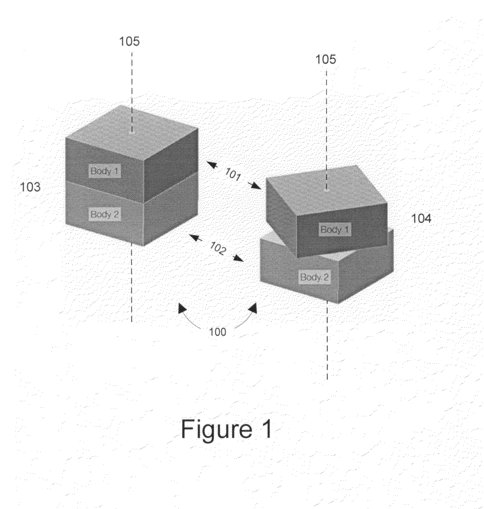
[0019]The present invention is directed at magnetic detents and systems employing magnetic detents. FIG. 1 illustrates the general principle of a magnetic detent. Depicted in FIG. 1 is detent 100 comprising a first body 101 and second body 102. In this example, first detent body 101 and second detent body 102 are adapted to rotate about a common axis of rotation 105. FIG. 1 depicts detent 100 in two detent positions 103 and 104. When detent bodies 101 and 102 are in one of the two detent positions, they are in a configuration of relative stability with respect to each other. Depending on the strength of magnetic forces holding detent body 101 and detent body 102 in a detent position, a small perturbation of an external force on either bodies may not move the detent bodies out of a detent position. If a small enough force is applied, a self-aligning force will arise to move the detent bodies 101 and 102 back to the initial detent position. A larger perturbation of an external force o...


PUM

PropertyMeasurementUnit
magneticaaaaaaaaaa
magnetic fieldsaaaaaaaaaa
tactile mechanical feelaaaaaaaaaa

Abstract

Various embodiments for magnetic detent assemblies provide for detent devices with improved performance and manufacturability. In one embodiment, magnetic detent assemblies provide for custom detent positions and custom force profiles by including a pair of unitary magnetic components each having a special geometry. In an embodiment, the changing area of overlap (and hence magnetic flux) between the magnetic components can give rise to the custom detent positions and custom force profiles. In a specific embodiment, the magnetic components can comprise an N-point star shaped geometry, where the number and distribution of the start wings can be varied to define customized detent positions and the contour of the star wings can be varied to create customized force profiles. In other embodiments, devices such as laptop computers and docking stations for handheld electronic devices can implement multi-position detent hinges with the magnetic detent assemblies.

Description

BACKGROUND OF THE INVENTION[0001]A detent is a catch or a lever mechanism that defines resting positions as one part of an assembly moves relative to another part. Conventional detent devices typically rely on mechanical means, such as a lever and socket combination, to restrict the movement of the system in defining the resting positions. One type of detent is a rotational device that divides the rotation of a wheel, shaft or hinge into discreet increments where the fixed discreet increments define the detent positions. These mechanical systems commonly employ a small gravity or spring actuated lever paired with a notched shaft to help define the detent positions.[0002]In addition to defining detent positions, some detent devices offer self-centering forces that help to align and move the detent bodies into detent positions when the detent bodies are perturbed from their detent positions. In mechanical detents, centering mechanisms can include a wide diversity of contraptions inclu...

Claims


Application Information

Patent Timeline
Patent Type & Authority Patents(United States)
IPC IPC(8): E05D11/10H01F7/20
CPCG06F1/1616G06F1/1679H01F7/0242G06F1/1681Y10T29/24Y10T16/5401
Inventor PREST, CHRISTOPHER D.
Owner APPLE INC
Why Eureka
Try Eureka