Projector that is capable of superimposing and displaying a visible image and an invisible infrared image

a projector and visible image technology, applied in the field of projectors, can solve the problems of inaccurate grasping of information, difficult to find necessary information, neglecting individual pieces, etc., and achieve the effect of easy discrimination

Active Publication Date: 2011-05-03
SEIKO EPSON CORP
View PDF18 Cites 17 Cited by
  • Summary
  • Abstract
  • Description
  • Claims
  • Application Information

AI Technical Summary

Benefits of technology

[0010]An advantage of some aspects of the invention is to provide a projector that alone is capable of superimposing and displaying a visible image and an invisible infrared image on one projection surface in order to control display images (images and videos) and is simple and excellent in portability.

Problems solved by technology

This is because, when an excessively large amount of information is displayed at a time, people cannot accurately grasp the information, for example, it is difficult to find necessary information in busy streets in large cities where a large number of signboards are hanged out, but also tend to neglect to pay attention to individual pieces of information.
As a growing social problem, presentation information and video information are photographed and diverted without permission of copyright holders.
Taking into account the fact that there is an increasing number of portable projectors according to a reduction in size of projectors, portability is impeded when the two projectors are used.
In particular, since the infrared image is an invisible image, the work cannot be performed visually.
Therefore, installability and usability are extremely deteriorated.
For example, when a lens is used for the projecting means, since a lens glass material forming the lens has wavelength dependency of a refractive index, an optical aberration such as a color aberration inevitably occurs.
However, when infrared light is irradiated on the light modulation element and the polarizers, the light modulation element and the polarizers are easily charged with heat compared with irradiation of visible light and deterioration of the light modulation elements and the polarizers tends to occur.

Method used


Image

  • Projector that is capable of superimposing and displaying a visible image and an invisible infrared image
  • Projector that is capable of superimposing and displaying a visible image and an invisible infrared image
  • Projector that is capable of superimposing and displaying a visible image and an invisible infrared image

Examples


first embodiment

[0049]A first embodiment of the invention will be hereinafter explained with reference to FIGS. 1 to 3.

[0050]In this embodiment, an example of the structure of a liquid crystal projector including four transmissive liquid crystal light valves is explained.

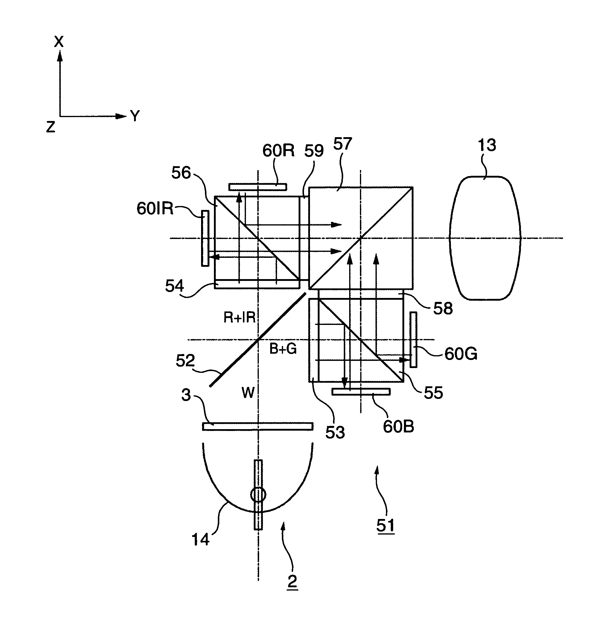
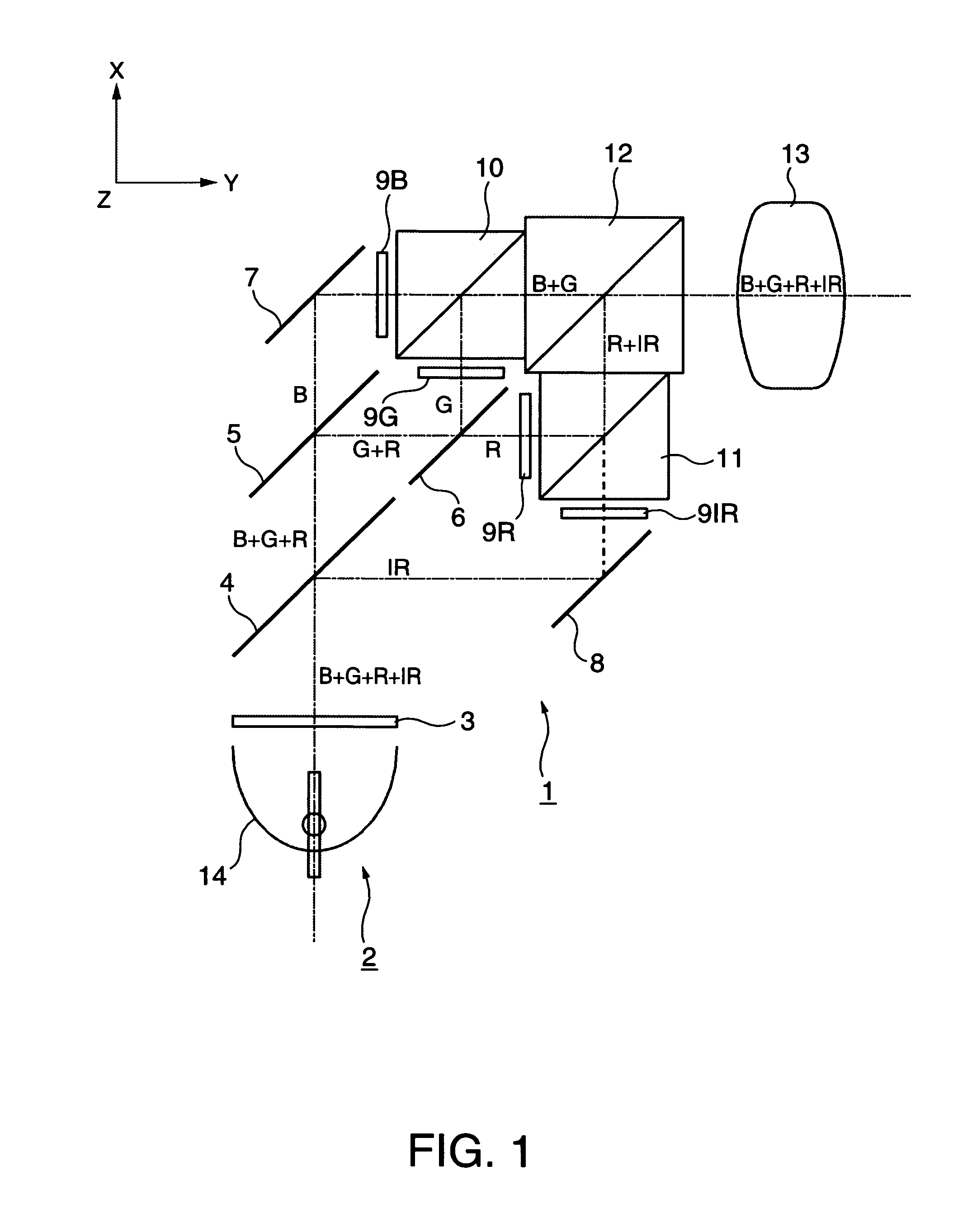
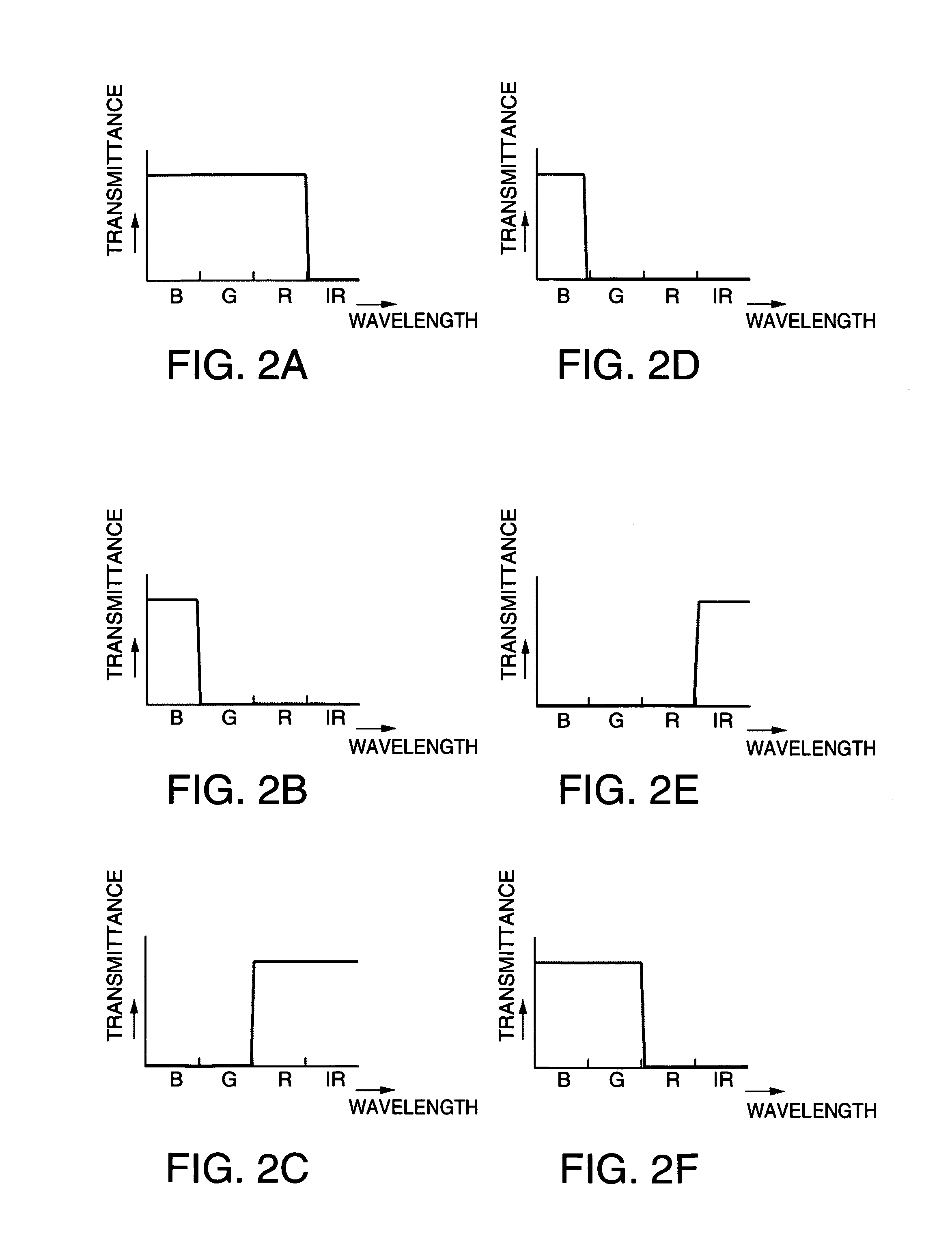
[0051]FIG. 1 is a schematic diagram of a projector according to this embodiment. FIGS. 2A to 2F are diagrams showing spectral characteristics of dichroic mirrors (dichroic prisms) used in the projector. FIG. 3 is an enlarged diagram of the periphery of a liquid crystal light valve used in the projector.

[0052]In the respective drawings referred to below, to make it easy to see respective components, dimensions and scales of positional relations are varied for the respective components.

[0053]A projector 1 according to this embodiment roughly includes, as shown in FIG. 1, a light source 2, an ultraviolet cut filter 3, dichroic mirrors 4, 5, and 6 (light separating means), reflection mirrors 7 and 8, liquid crystal light valves 9R, 9G,...

second embodiment

[0071]A second embodiment of the invention will be hereinafter explained with reference to FIG. 4.

[0072]The basic structure of a projector according to this embodiment is substantially the same as that of the projector according to the first embodiment. However, the projector according to this embodiment is different from the projector according to the first embodiment in that a light source for infrared light is provided independently from a white light source for visible light.

[0073]FIG. 4 is a schematic diagram of the projector according to this embodiment. In FIG. 4, components same as those shown in FIG. 1 referred to in the first embodiment are denoted by the same reference numerals and signs and detailed explanation of the components are omitted.

[0074]Most of discharge-type light sources such as a high pressure mercury lamp and a metal halide lamp radiate infrared light together with visible light. However, in general, it is difficult to obtain infrared light with high intens...

third embodiment

[0080]A third embodiment of the invention will be hereinafter explained with reference to FIG. 5.

[0081]A projector according to this embodiment includes, unlike the projectors according to the first and second embodiments, four light sources having light emission wavelength regions different from one another.

[0082]FIG. 5 is a schematic diagram of the projector according to this embodiment. In FIG. 5, components same as those shown in FIGS. 1 and 4 referred to in the first embodiment are denoted by the same reference numerals and signs and detailed explanation of the components are omitted.

[0083]A projector 31 according to this embodiment includes, as shown in FIG. 5, a light source for blue light 32B that emits blue light, a light source for green light 32G that emits green light, a light source for red light 32R that emits red light, and a light source for infrared light 32IR that emits infrared light. Solid-state light sources such as an LED, a laser, an EL (Electro-Luminescence) ...


PUM


Abstract

A projector includes a light source that emits light including visible light and infrared light, a light separating unit that separates the light from the light source into lights in plural different wavelength regions, at least one light modulation element for visible light that modulates visible light separated by the light separating unit, at least one light modulation element for infrared light that modulates one kind of infrared light or at least two kinds of infrared light in wavelength regions different from each other separated by the light separating unit, a light combining unit that combines the modulated light modulated by the light modulation element for visible light and the modulated light modulated by the light modulation element for infrared light into one to form combined light, and a projecting unit that projects and displays the combined light combined by the light combining unit on a projection surface. The projector superimposes and displays a visible light image formed by the light modulation element for visible light and an infrared image formed by the light modulation element for infrared light on the identical projection surface.

Description

BACKGROUND[0001]1. Technical Field[0002]The present invention relates to a projector, and, more particularly to a projector that can display a visible image and an infrared image on one screen.[0003]2. Related Art[0004]A projector that displays an optical image, which is image information formed on a light modulation element, on a screen in enlargement is highly consistent with digital apparatuses such as a computer. Therefore, the projector is widely used mainly for presentation, information provision, and video entertainment. Since a major function of a general display apparatus including the projector is to communicate some meaningful information to people, image information is usually displayed as a visible image that people can visually recognize. Therefore, a general projector selects visible light from light radiated from a light source and uses the visible light as illumination light to perform image display.[0005]It is said that, when meaningful information is displayed for...

Claims


Application Information

Patent Timeline
Patent Type & Authority Patents(United States)
IPC IPC(8): G03B21/00
CPCG03B21/14G03B21/26G03B21/006G03B21/2066G03B33/12
Inventor ITO, YOSHITAKA
Owner SEIKO EPSON CORP
Why Eureka
Try Eureka