Self-calibration algorithms in a small motor driver IC with an integrated position sensor

a self-calibration algorithm and position sensor technology, applied in the direction of electric programme control, program control, instruments, etc., can solve the problems of reduced range of travel, offset in the start-of-travel position of the motor, and difficulty in achieving precise linear motion control of such motors, so as to improve speed, enhance accuracy, and improve accuracy

Active Publication Date: 2011-05-03
ALLEGRO MICROSYSTEMS INC
View PDF34 Cites 88 Cited by
  • Summary
  • Abstract
  • Description
  • Claims
  • Application Information

AI Technical Summary

Benefits of technology

Particular implementations of the invention may provide one or more of the following advantages. The motion control device can achieve accurate linear motion control over the position of any motor (e.g., VCM) that it controls, despite significant variations in the start-of-travel and end-of-travel positions that may be observed between individual motors. Besides enhanced accuracy, other benefits to the user or application include repeatability as well as improved speed, for example, reduced focusing time in camera lens focusing modules. In addition, external microcontroller-executed calibration routines are no longer necessary.

Problems solved by technology

When driving small motors, mechanical tolerances and hysteresis effects, as well as magnetic circuit variations, can cause offset in the motor start-of-travel (or home) position and reduced range of travel.
Thus, precise linear motion control of such motors may be difficult to achieve without some type of calibration.

Method used


Image

  • Self-calibration algorithms in a small motor driver IC with an integrated position sensor
  • Self-calibration algorithms in a small motor driver IC with an integrated position sensor
  • Self-calibration algorithms in a small motor driver IC with an integrated position sensor

Examples


Embodiment Construction

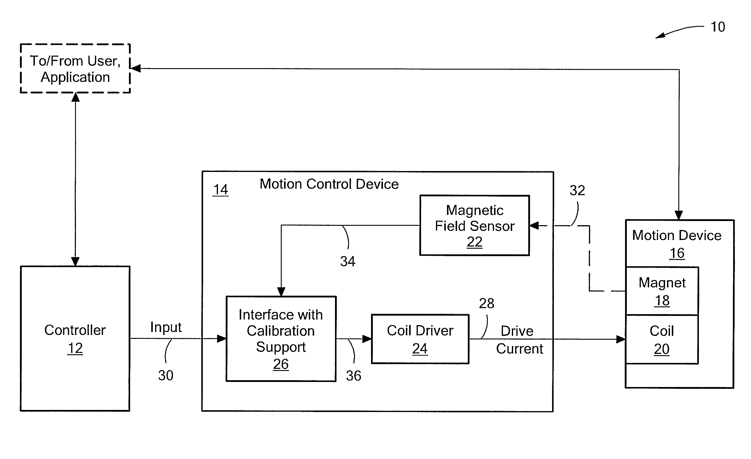
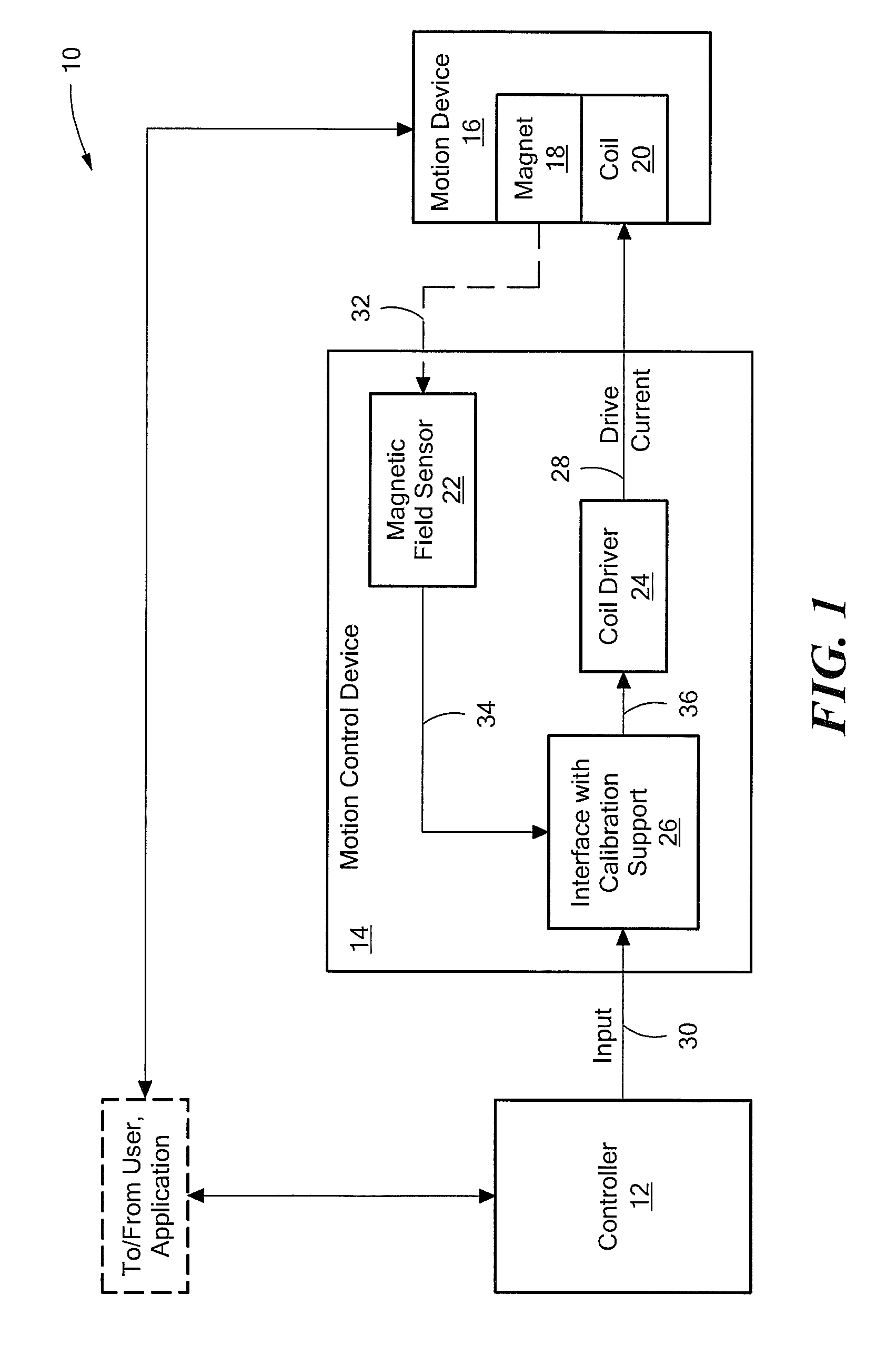
FIG. 1 shows an exemplary control system 10 that provides closed-loop motion control to a positioning application. The control system 10 includes a controller 12 connected to a motion control device (or “device”) 14. The control system 10 also includes a motion device 16, which includes an assembly having a magnet 18 and a coil 20. The magnet / coil assembly connects to a device or structure to be moved for a given application. In one embodiment, described herein, the magnet 18 is movable relative to the coil 20 and the control system 10 controls the movement of the magnet 18 with the coil 20. The motion device 16 may be any type of linear motion device, for example, a linear motor such as a voice coil motor (VCM). The positioning application may be any application that utilizes a displacement produced by the motion device.

The motion control device 14 includes a position sensor shown as a magnetic field sensor 22, a coil driver 24 and an interface with calibration support 26. The magn...


PUM


Abstract

A motion control device for controlling a motor is presented. The motion control device is operable to scale or adjust an input relative to an input range that is based on calibration values and to use that scaled input to produce a drive signal to drive the motor. The motion control device performs a self-calibration to produce the calibration values. The self-calibration involves measuring home position and full travel position values for the motor.

Description

STATEMENT REGARDING FEDERALLY SPONSORED RESEARCHNot applicable.FIELD OF THE INVENTIONThis invention relates generally to calibration techniques for motor control.BACKGROUND OF THE INVENTIONWhen driving small motors, mechanical tolerances and hysteresis effects, as well as magnetic circuit variations, can cause offset in the motor start-of-travel (or home) position and reduced range of travel. These home position offsets and range of travel limitations vary from motor to motor. Thus, precise linear motion control of such motors may be difficult to achieve without some type of calibration.In some positioning applications, the microcontroller or processor that issues the drive signal (i.e., position) requests also performs a calibration routine. The calibration routine may use output signal data from a number of different components, including a position sensor, to compensate for offset and range of travel differences. The microcontroller must store and subsequently use the calibration...

Claims


Application Information

Patent Timeline
Patent Type & Authority Patents(United States)
IPC IPC(8): G05D23/275
CPCG05B19/19H02P25/028G05B2219/41099G05B2219/42152G05B2219/45178G05B2219/41337H02P25/034
Inventor VIG, RAVIDAVID, PAULMILANO, SHAUN D.DOOGUE, MICHAEL C.HAAS, DAVID J.
Owner ALLEGRO MICROSYSTEMS INC
Why Eureka
Try Eureka