Variable valve timing system

a valve timing and variable technology, applied in non-mechanical valves, electrical control, instruments, etc., can solve the problems of limiting the rate of change in the opening/closing timing, the change in the undesirable direction of the opening/closing timing, etc., to achieve the effect of less negative influence on the valve timing control and more stab execution

Inactive Publication Date: 2011-05-10
TOYOTA JIDOSHA KK
View PDF12 Cites 4 Cited by
  • Summary
  • Abstract
  • Description
  • Claims
  • Application Information

AI Technical Summary

Benefits of technology

[0013]With the variable valve timing system according to the first aspect of the invention, the duty ratio of the operation command signal, which indicates the control mode and the operating direction in which the actuator should be operated, is set on one of the higher side or the lower side with respect to the boundary value based on the operating direction. In addition, the duty ratio close to the boundary value indicates, in each of the operating directions, the control mode in which the rate of change in the opening / closing timing is relatively low. Accordingly, even when the drive control unit falsely recognizes the duty ratio of the operation command signal, a false recognition concerning the operating direction is prevented. Such false recognition may cause the opening / closing timing to change in an undesirable direction. Even if the operating direction is falsely recognized, the rate of change in the opening / closing timing is restricted. The control signal contains multiple operation command items. In addition, the operation command signal for the actuator is appropriately set such that, even when the duty ratio of the control signal is falsely recognized, the negative influence on the valve timing control is minimized. In this way, the valve timing control is executed more stably.
[0015]Thus, the effect of preventing the drive control unit from falsely recognizing the direction in which the actuator should be operated is enhanced.
[0018]Thus, in the configuration in which the actuator is the electric motor and the control modes include the first control mode (the rotational speed control mode) in which the rotational speed control over the electric motor is executed, and the second control mode (the constant electric power control mode) in which the electric power supplied to the electric motor is fixed, the same effects as those produced by the variable valve timing system described above can be obtained.

Problems solved by technology

Such false recognition may cause the opening / closing timing to change in an undesirable direction.
Even if the operating direction is falsely recognized, the rate of change in the opening / closing timing is restricted.

Method used


Image

  • Variable valve timing system
  • Variable valve timing system
  • Variable valve timing system

Examples


Embodiment Construction

[0043]Hereafter, an embodiment of the invention will be described with reference to the accompanying drawings. In the following description, the same or corresponding elements will be denoted by the same reference numerals. The names and functions of the elements having the same reference numerals are also the same. Accordingly, the descriptions concerning the elements having the same reference numerals will be provided only once below.

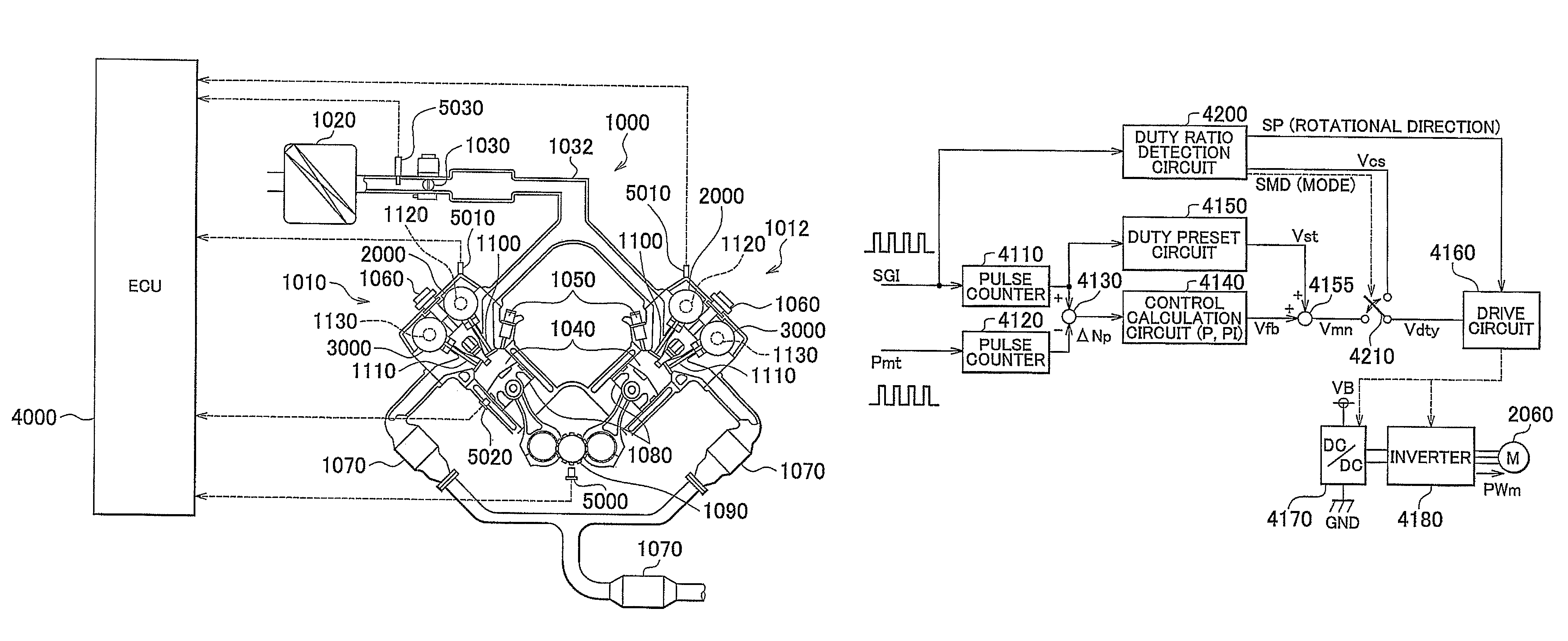
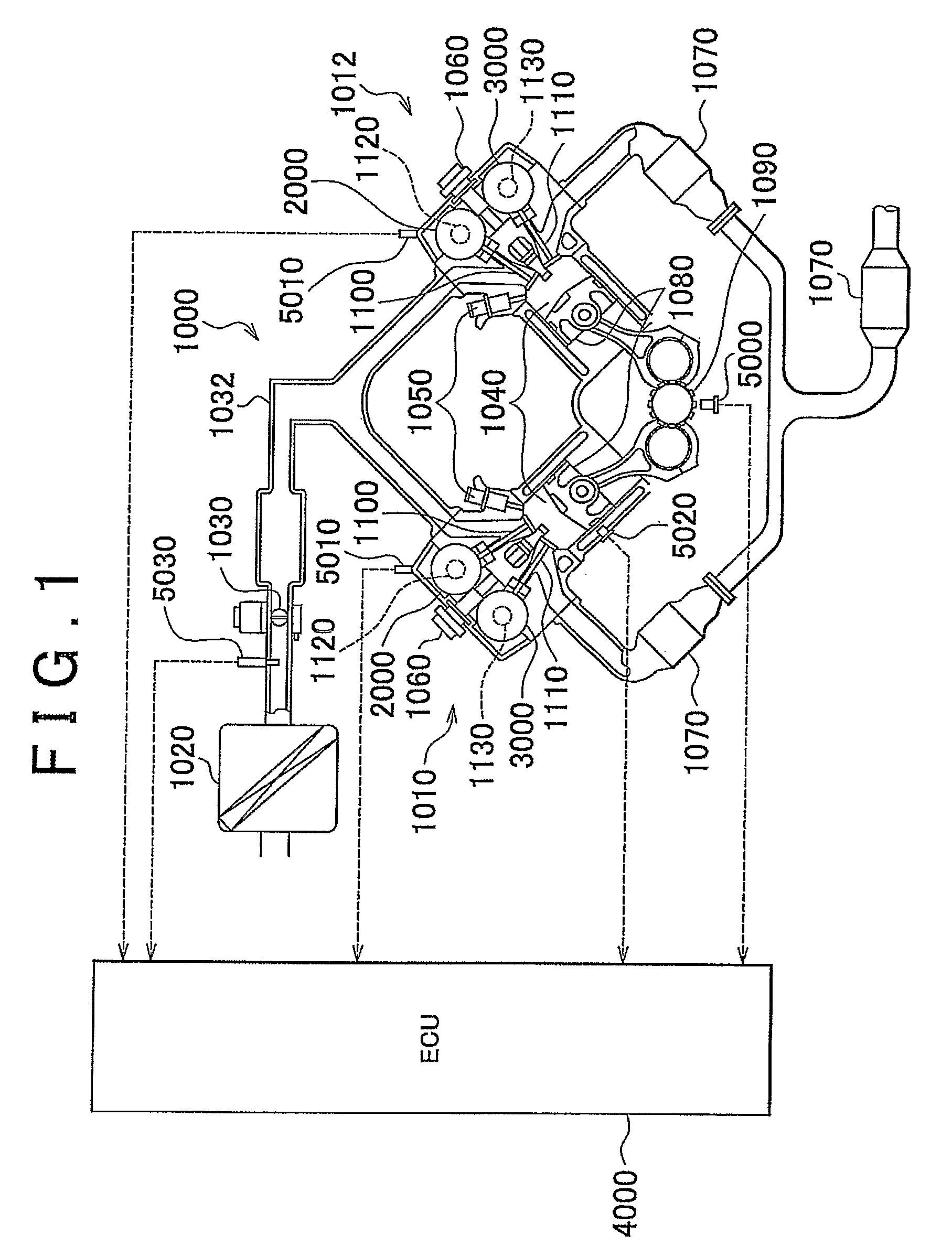
[0044]First, a vehicle engine provided with a variable valve timing system according to the embodiment of the invention will be described with reference to FIG. 1.

[0045]An engine 1000 is an eight-cylinder V-type engine including a first bank 1010 and a second bank 1012 each of which has four cylinders therein. Note that, the variable valve timing system according to the embodiment of the invention may be applied to any types of engines. Namely, the variable valve timing system may be applied to engines other than an eight-cylinder V-type engine.

[0046]...


PUM


Abstract

An ECU transmits a pulsed operation command signal, indicating operation commands for an electric motor used as a VVT actuator, to an electric-motor EDU. The electric-motor EDU recognizes the combination of the direction in which the actuator should be operated (actuator operation direction) and the control mode based on the duty ratio of the operation command signal, and the rotational speed command value based on the frequency of the operation command signal. The electric-motor EDU controls the electric motor according to the control commands. The duty ratio indicating the combination is set such that even if the duty ratio is falsely recognized, a false recognition concerning the actuator operation direction is prevented, such false recognition causing the valve phase to change in an undesirable direction, and even if the actuator operation direction is falsely recognized, the rate of change in the phase is restricted.

Description

BACKGROUND OF THE INVENTION[0001]1. Field of the Invention[0002]The invention relates generally to a variable valve timing system, and, more specifically, to a variable valve timing system that changes the opening / closing timing of a valve by an amount of change corresponding to the operation amount of an actuator.[0003]2. Description of the Related Art[0004]A variable valve timing (VVT) system that changes the phase (i.e., crank angle), at which an intake valve or an exhaust valve is opened / closed, based on the engine operating state has been used. Such variable valve timing system changes the phase of the intake valve or the exhaust valve by rotating a camshaft, which opens / closes the intake valve or the exhaust valve, relative to, for example, a sprocket. The camshaft is rotated hydraulically or by means of an actuator, for example, an electric motor.[0005]For example, Japanese Patent Application Publication No. 2005-120874 (JP-A-2005-120874) describes a valve timing adjustment d...

Claims


Application Information

Patent Timeline
Patent Type & Authority Patents(United States)
IPC IPC(8): F01L1/34
CPCF01L1/352F01L1/356F02D41/0002F02D41/221Y02T10/42F02D2041/001F02D2041/2027Y02T10/40Y02T10/12
Inventor MASHIKI, ZENICHIROINOUE, YASUMICHITAKAGI, NOBORUURUSHIHATA, HARUYUKI
Owner TOYOTA JIDOSHA KK
Why Eureka
Try Eureka