Electrophoresis unit and electrophoretic analysis method
a technology of electrophoretic analysis and electrophoretic analysis, which is applied in the direction of fluid pressure measurement, liquid/fluent solid measurement, peptide measurement, etc., can solve the problem that the measured signal value may exceed the detection limit during analysis, and achieve the effect of avoiding re-measurement and extending the dynamic range of the detector
- Summary
- Abstract
- Description
- Claims
- Application Information
AI Technical Summary
Benefits of technology
Problems solved by technology
Method used
Image
Examples
first embodiment
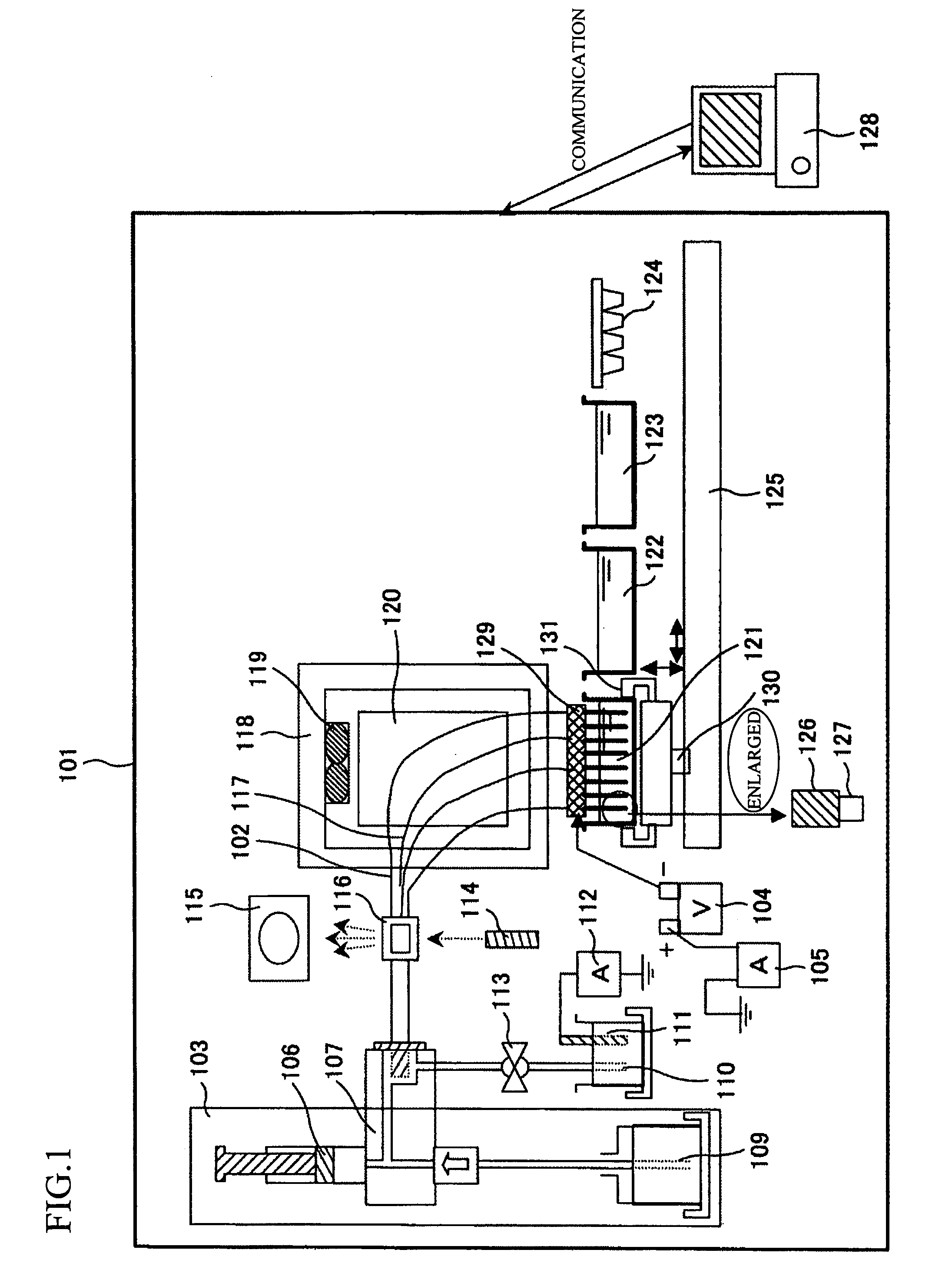
[0027]FIG. 1 is an outline drawing of an electrophoresis unit according to the present embodiment. The configuration of the present apparatus will be described below with reference to FIG. 1.
[0028]The present apparatus includes a detection part 116 for optically detecting a sample, a thermostatic oven 118 for maintaining a capillary at a constant temperature, an auto sampler 125 for transporting various containers to a capillary cathode electrode end, a high-voltage power supply 104 for applying a high voltage to the capillary, a first ammeter 105 for detecting a current originating from the high-voltage power supply, a second ammeter 112 for detecting a current flowing to an anode electrode, a capillary array 117 consisting of a single or a plurality of capillaries 102, and a pump mechanism 103 for injecting a polymer into a capillary.
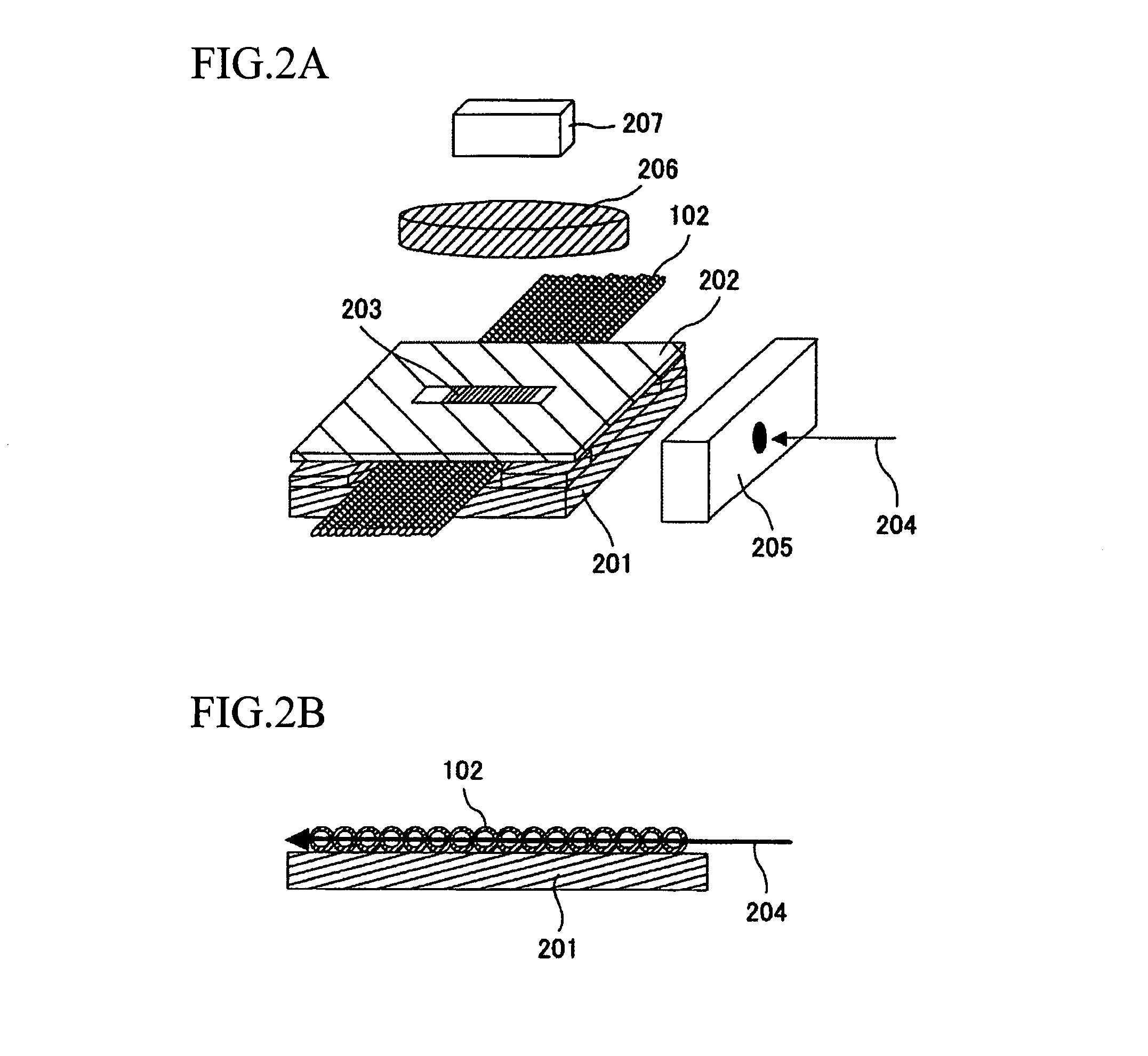
[0029]The capillary array 117 is a replacement member including 16 capillaries and includes a load header 129, the detection part 116, and a capillar...
second embodiment
[0065]A second embodiment will be described below.
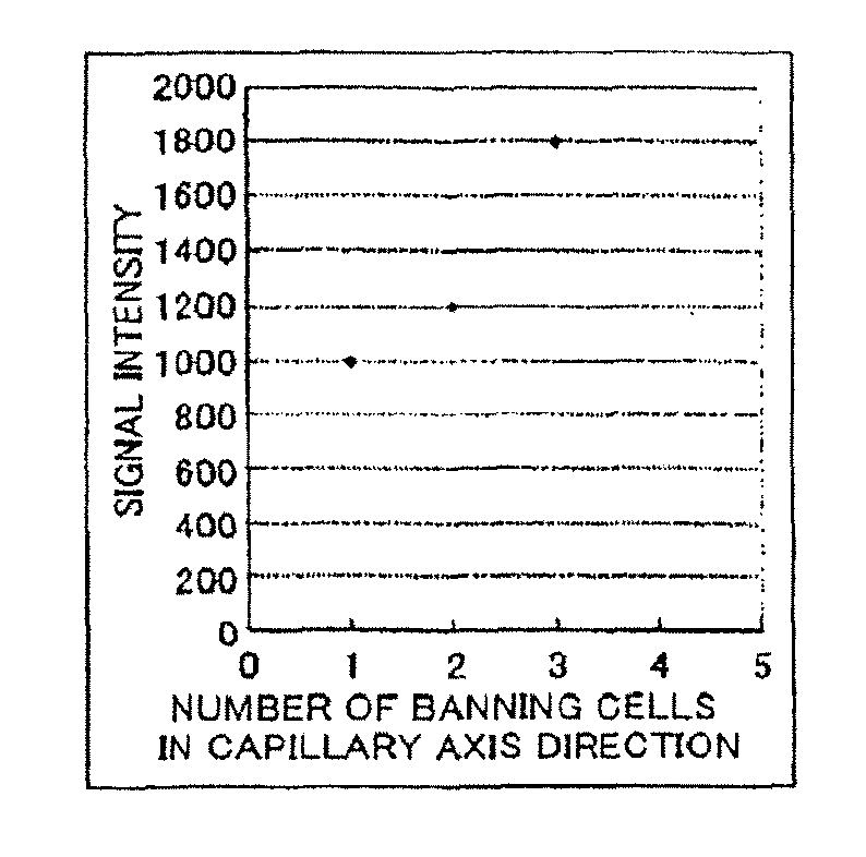
[0066]In the second embodiment, reduction in acquired signal intensity by a method of controlling a data binning area of a detector, instead of the excitation light irradiation time to a sample, will be described. In FIG. 6A, acquired data is saturated when the number of data integrating cells in the capillary space direction is 3. Thus, as shown in FIG. 6B, if the number of data integrating cells in the capillary space direction is 1 with the same sampling time and excitation light irradiation time, the number of cells to be integrated will be ⅓ and thus, acquired signal intensity by a detector will be smaller to fall below the limit value of detection so that correct data can be obtained. In this case, as shown in FIG. 6C, like the first embodiment, signal intensity values when the number of cells is changed need to be measured in each capillary when spectral calibration data is obtained. Based on this relationship, the reduced val...
third embodiment
[0070]A third embodiment will be described below.
[0071]While a laser is used as a light source in the first embodiment to adjust the irradiation time of excitation light by a shutter, a case in which an LED is used as an excitation light source and the LED is caused to blink at high speed will be described in the present embodiment with reference to FIG. 7A and FIG. 7B. Because an LED light source 701 has a fast response time of several μsec to ON / OFF switching, the shutter is not necessary when the excitation time is controlled by ON / OFF. By driving ON / OFF of the LED light source 701 in synchronization with timing of data acquisition of the optical detector 207, it becomes possible to adjust the irradiation time to samples and to prevent saturation of acquired signal values.
PUM
| Property | Measurement | Unit |
|---|---|---|
| diameter | aaaaa | aaaaa |
| time | aaaaa | aaaaa |
| time | aaaaa | aaaaa |
Abstract
Description
Claims
Application Information
 - R&D
- Intellectual Property
- Life Sciences
- Materials
- Tech Scout
- Unparalleled Data Quality
- Higher Quality Content
- 60% Fewer Hallucinations
Browse by: Latest US Patents, China's latest patents, Technical Efficacy Thesaurus, Application Domain, Technology Topic, Popular Technical Reports.
© 2025 PatSnap. All rights reserved.Legal|Privacy policy|Modern Slavery Act Transparency Statement|Sitemap|About US| Contact US: help@patsnap.com


