

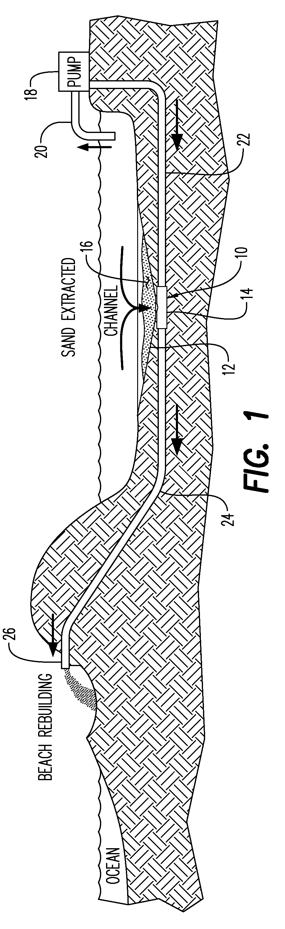
Catch basin for salt water sand
a technology for salt water sand and catch basins, which is applied in the direction of water cleaning, liquid displacement, separation processes, etc., can solve the problems of sandbars creating serious environmental and navigational hazards, requiring at least periodic dredging at great expense, and disrupting water traffic, and achieves the effect of smooth drawing of sand and sedimen
- Summary
- Abstract
- Description
- Claims
- Application Information
AI Technical Summary
Benefits of technology
Problems solved by technology
Method used
Image

Examples
second embodiment
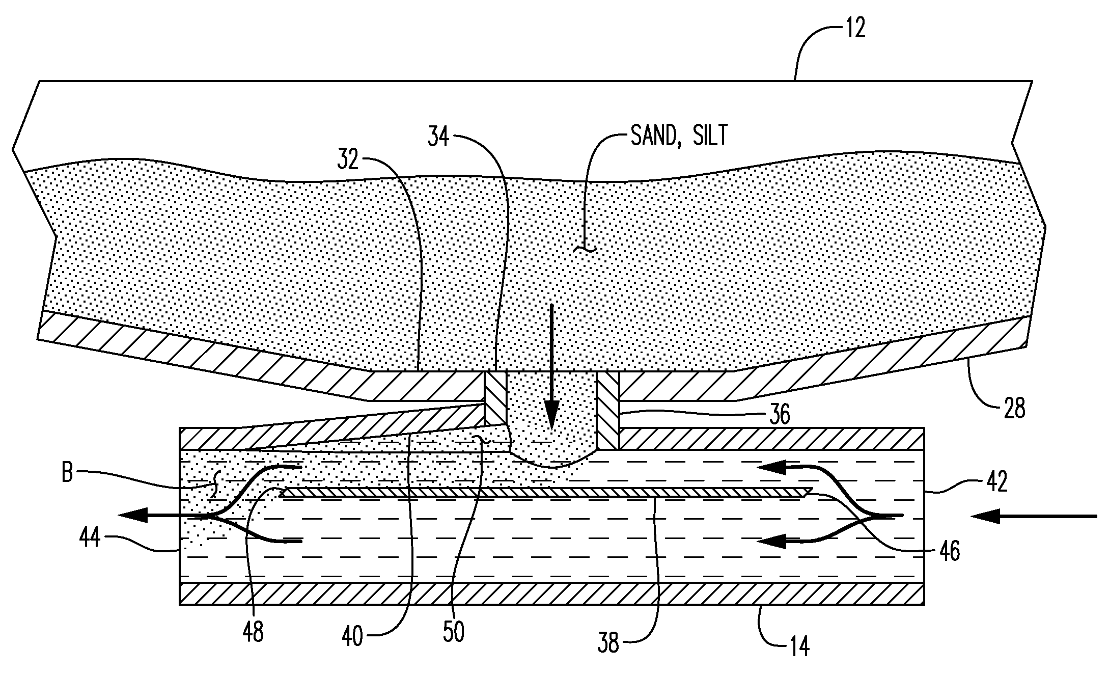
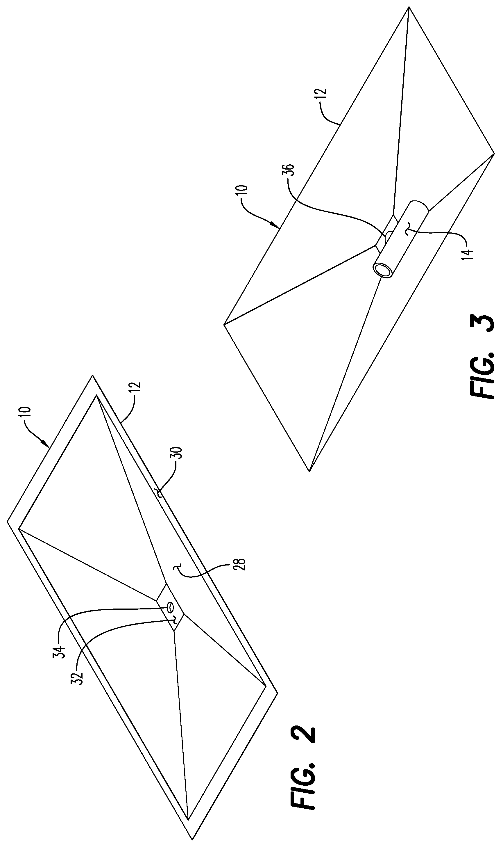
[0055]Referring now to FIGS. 10 to 14, and the catch basin is there shown generally at numeral 60 and includes a basin 62 having sloping walls shown typically at 66 which are steeper in nature and represent a more severe sidewall angle within the scope of this disclosure. This sidewall angle is provided where the sand and silt has been determined to be less susceptible to the downward sliding movement by gravity down to the bottom 64 and into the transfer tube 14 as previously described. Flanges 62 extending along each distal edge of each of the side panels 66 add strength and also provide a level of vertical flotation when the catch basin assembly 60 is deployed to prevent excessive sinking of the catch basin 62 into the soil bottom. As best seen in FIG. 13, the longitudinal side panels are oriented at approximately 135° degrees included angle to the bottom 68, while in FIG. 14, that included angle is approximately 120°.
embodiment 80
[0056]Yet another embodiment of the invention is shown generally at numeral 80 as seen in FIGS. 15 to 19. In this embodiment 80, the transfer tube 92 is as previously described having a horizontally extending catch plate 96 within the interior of the transfer tube 92, directly below the aperture 88 which extends from the bottom 86 downwardly into the interior of the transfer tube 92. The cavity 98 also functions as previously described.
[0057]The inlet and outlet conduits 90 and 94 extend diagonally along and within a tunnel at 100 and 104 affixed and extending longitudinally along the lower surfaces of the end side panels shown typically at 84. These tunnels 100, 102 and 104 serve to affix the inlet conduit 90, the transfer tube 92 and the outlet conduit 94 in protected position to facilitate deployment and interconnection to the remaining conduit structure and pump as previously described. The bottom 86 is a double bottom as best seen in FIGS. 15, 17 and 19 so as to maintain a smoo...
PUM
| Property | Measurement | Unit |
|---|---|---|
| obtuse angle | aaaaa | aaaaa |
| depth | aaaaa | aaaaa |
| angle | aaaaa | aaaaa |
Abstract
Description
Claims
Application Information