
Stacked PTC thermistor and process for its production

a ptc thermistor and stacked technology, applied in the direction of positive temperature coefficient thermistors, basic electric elements, electric apparatus, etc., can solve the problem of insufficient jump characteristic, and achieve the effect of excellent jump characteristic, selective preference distribution of alkali metal elements, and easy segregation

Inactive Publication Date: 2011-05-17
TDK CORPARATION
View PDF14 Cites 2 Cited by
  • Summary
  • Abstract
  • Description
  • Claims
  • Application Information

AI Technical Summary

Benefits of technology

The solution effectively increases the jump characteristic while keeping room temperature resistivity low, enabling more reliable operation by promoting selective oxidation at grain boundaries and voids, thus achieving a high jump characteristic with low room temperature resistivity.

Problems solved by technology

However, investigation by the present inventors has revealed that while the stacked PTC thermistor disclosed in Japanese Patent Publication No. 3636075 allows the room temperature resistivity to be reduced, it cannot exhibit a sufficient jump characteristic.

Method used


Image

  • Stacked PTC thermistor and process for its production
  • Stacked PTC thermistor and process for its production
  • Stacked PTC thermistor and process for its production

Examples


example 1

Fabrication of Stacked PTC Thermistor

[0074]First, as starting powders for formation of the semiconductor ceramic layer there were prepared powders of BaCO3, TiO2, Gd2O3, SiO2 and Mn(NO3)2.6H2O. The starting powders were weighed out in amounts for a barium titanate-based compound composition according to formula (6) above. The weighed amounts of each of the starting powders were placed in a nylon pot together with purified water and a pulverizing ball and mixed for 6 hours and dried to obtain a mixed powder.

[0075]After subsequent pre-molding of the mixed powder, it was held for 4 hours in air at 1150° C. and calcined to obtain a calcined body. The calcined body was shredded to form a calcined powder with a mean particle size of 1 μm. Next, the calcined powder was placed in a nylon pot together with purified water and a pulverizing ball, and prescribed amounts of a solvent, binder and plasticizer were added and mixed therewith for about 20 hours using a triple roll to obtain a green s...

examples 2-10

[0082]Stacked PTC thermistors for Examples 2-10 were fabricated by the same method as Example 1, except that the alkali metal salts shown in Table 1 were used as alkali metal salts instead of Li2O.

example 11

Fabrication of Stacked PTC Thermistors

[0101]After weighing out BaCO3, TiO2, Gd2O3 and Nb2O5 as starting powders in amounts so that the barium titanate-based compound had the composition shown in the following formula (11), they were placed in a nylon pot together with purified water and a pulverizing ball, mixed for 6 hours and then dried to obtain a mixed powder.

(Ba0.9985Gd0.0015)0.995(Ti0.9985Nb0.0015)O3  (11)

[0102]A porous sintered compact was prepared in the same manner as Example 1, except for using this mixed powder. The prepared sintered compact was then impregnated with an aqueous solution containing an alkali metal salt, to adhere the alkali metal salt to the sintered compact. The alkali metal salt used was NaNO3 with a molecular weight of 84.995. The alkali metal (Na) concentration in the aqueous solution of the alkali metal salt (NaNO3) was 0.08 mol % as alkali metal element (Na element).

[0103]After coating the edge faces 4a, 4b of the body 4 with Ag—Pd paste, it was bake...


PUM

PropertyMeasurementUnit
temperatureaaaaaaaaaa
thicknessaaaaaaaaaa
dew pointaaaaaaaaaa

Abstract

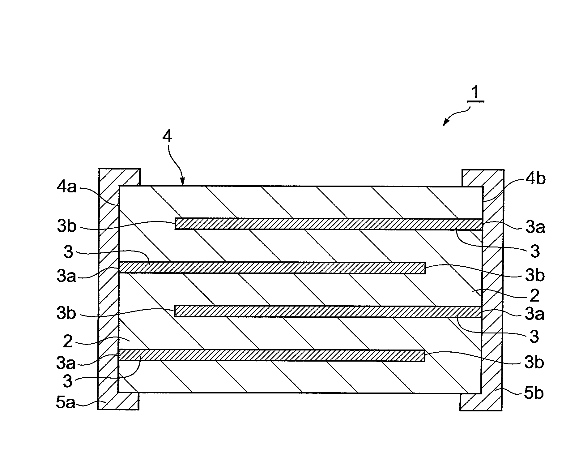
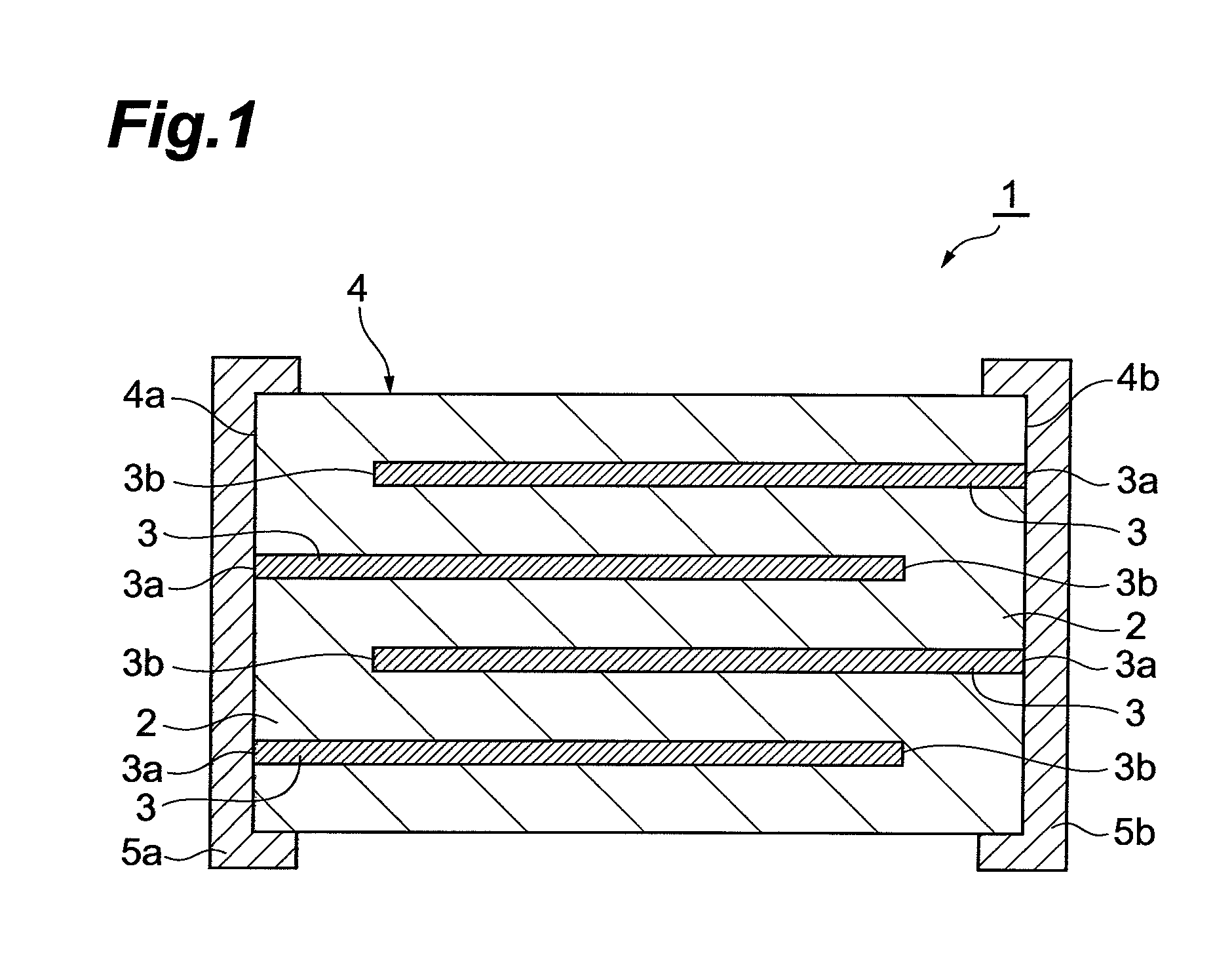
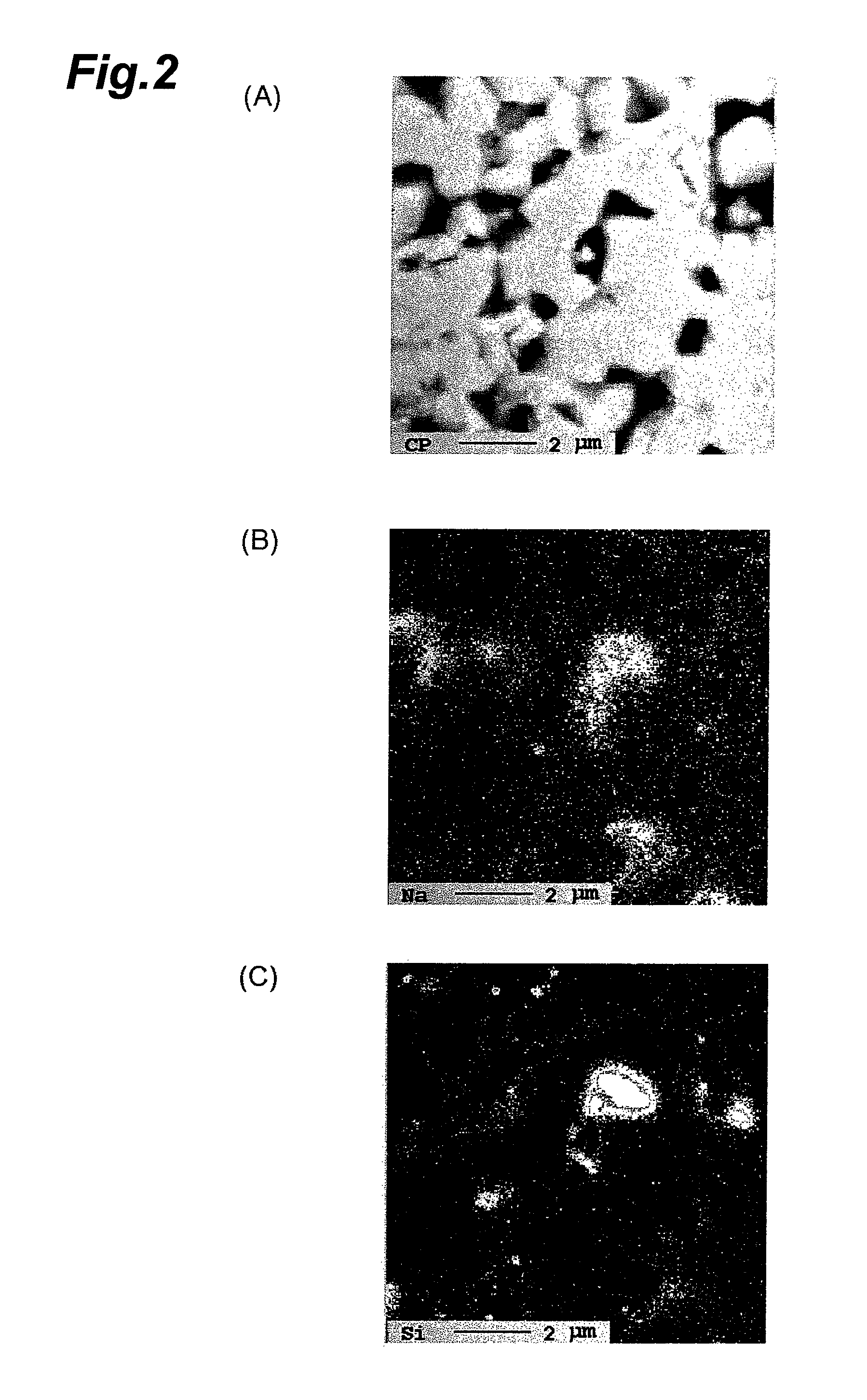
A stacked PTC thermistor 1 comprises a body 4 obtained by alternating lamination of a semiconductor ceramic layer 2 and an internal electrode 3, and a pair of external electrodes 5a, 5b provided at the edge faces 4a, 4b of the body 4 and electrically connected with the internal electrode 3. The semiconductor ceramic layer 2 is composed of a porous sintered compact containing crystal grains of a barium titanate-based compound, and an alkali metal element is preferentially distributed in at least one of the grain boundaries and voids of the sintered compact.

Description

BACKGROUND OF THE INVENTION[0001]1. Field of the Invention[0002]The present invention relates to a stacked PTC thermistor and to a process for its production.[0003]2. Related Background Art[0004]PTC (Positive Temperature Coefficient) thermistors are known as thermistors with positive resistance temperature characteristics, whereby the resistance increases with increased temperature. PTC thermistors are utilized in self-regulating heating units, overcurrent protection elements, temperature sensors and the like. As such PTC thermistors, there have conventionally been implemented single-layer PTC thermistors comprising a semiconductor ceramic layer with conductivity imparted by adding a trace amount of a rare earth element to barium titanate (BaTiO3) as the main component, and a pair of external electrodes sandwiching the semiconductor ceramic layer.[0005]In recent years, demand has sharply increased for PTC thermistors with sufficiently low resistivity at ordinary temperature during n...

Claims


Application Information

Patent Timeline
Patent Type & Authority Patents(United States)
IPC IPC(8): H01C7/10
CPCC04B35/4682H01C7/025C04B35/6262Y10T29/49082C04B2235/3201C04B2235/3203C04B2235/3208C04B2235/3213C04B2235/3224C04B2235/3225C04B2235/3227C04B2235/3229C04B2235/3239C04B2235/3251C04B2235/3262C04B2235/3279C04B2235/3281C04B2235/3284C04B2235/3409C04B2235/3418C04B2235/3427C04B2235/44C04B2235/442C04B2235/443C04B2235/444C04B2235/448C04B2235/6025C04B2235/616C04B2235/652C04B2235/6582C04B2235/663C04B2235/77C04B2235/85Y10T29/49085
Inventor ITOH, KAZUHIKOKAKINUMA, AKIRAHITOMI, ATSUSHI
Owner TDK CORPARATION
Learn More