Retardation film, polarizing film, liquid crystal display, and method of designing retardation film

a retardation film and polarizing film technology, applied in the direction of polarizing elements, thin material handling, instruments, etc., can solve the problems of difficult widening of viewing angles, difficult to achieve high contrast ratio, and inability to achieve contrast ratio, etc., to achieve wide viewing angles, high display quality, and suitable for large tv

Active Publication Date: 2011-05-24
SHARP KK
View PDF42 Cites 20 Cited by
  • Summary
  • Abstract
  • Description
  • Claims
  • Application Information

AI Technical Summary

Benefits of technology

[0133]According to the retardation film of the present invention, the maintenance of orthogonality at the oblique viewing angle of the polarizing elements of Cross-Nicol arrangement is performed in a region of wide wavelength of red, blue, and green, and the light leakage and the coloration phenomenon at the oblique viewing angle are effectively prevented in the liquid crystal display of vertical alignment mode (VA mode), in plane switching mode (IPS mode) etc. The liquid crystal display using such retardation film achieves wider viewing angle, obtains high display quality, and is particularly suitable in large television.

Problems solved by technology

Therefore the liquid crystal display of TN mode is industrially mature, but there is room for improvement in the way that high contrast ratio is difficult to achieve.
Therefore, the liquid crystal display of VA mode can easily achieve a very high contrast ratio, which is not possible with the TN mode.
However, in the liquid crystal display of VA having the configuration described above, there is room for improvement in the way that the viewing angle is difficult to widen.
The conventional liquid crystal display has an essential problem in that the retardation film can be designed only at the single wavelength due to restrictions in types and stacking orders of the retardation film used, the fact that the supporting layer (presently, most general layer is a triacetyl cellulose film=TAC film) for protecting the polarizing element unintentionally has retardation and the like.
Therefore, in the prior art described above, the design of the retardation is very difficult, and the most suitable design that takes even the wavelength property into consideration is substantially not possible.

Method used


Image

  • Retardation film, polarizing film, liquid crystal display, and method of designing retardation film
  • Retardation film, polarizing film, liquid crystal display, and method of designing retardation film
  • Retardation film, polarizing film, liquid crystal display, and method of designing retardation film

Examples


embodiment 1

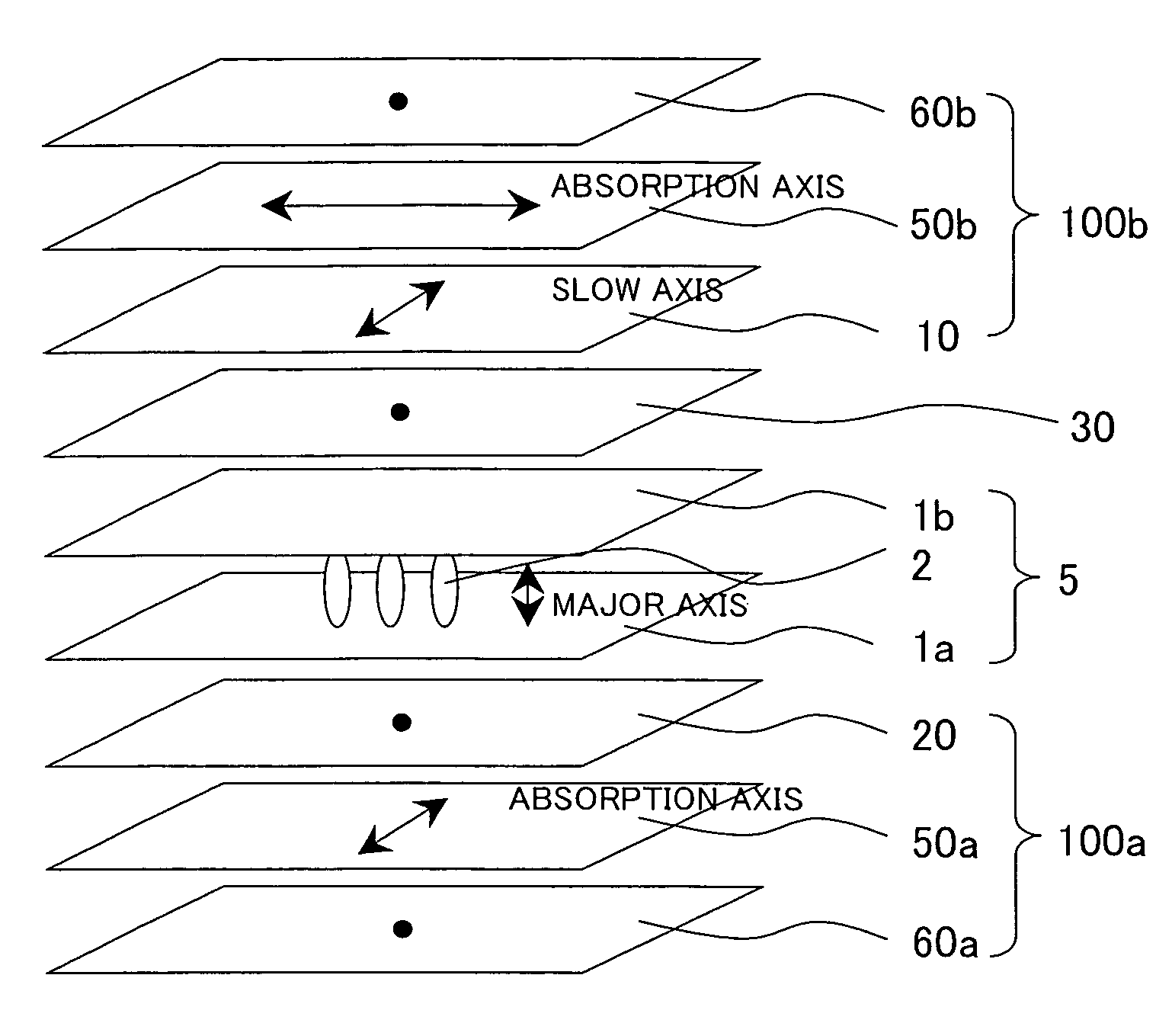
[0186]FIG. 19-1 is a perspective view showing in a frame format the configuration of the liquid crystal display of Embodiment 1.

[0187]As shown in FIG. 19-1, the liquid crystal display of Embodiment 1 according to the present invention is a VA mode liquid crystal display realized by arranging a polarizing film 100a obtained by stacking in order the positive C plate 20 designed for the entire region of the visible wavelength of the present invention, the polarizing element 50a, and the TAC film 60a on one outer side of the VA mode liquid crystal cell 5, where the liquid crystal 2 having negative dielectric constant anisotropy is sandwiched between two upper and lower substrates 1a, 1b performed with vertical alignment process on the surface so that the side of the positive C plate 20 is positioned on the liquid crystal cell 5 side; arranging the negative C plate 30 designed for the entire region of the visible wavelength of the present invention on the other outer side of the VA mode ...

embodiment 2

[0191]FIG. 20 is a perspective view showing in a frame format the configuration of the liquid crystal display of Embodiment 2.

[0192]As shown in FIG. 20, the liquid crystal display of Embodiment 2 according to the present invention is a VA mode liquid crystal display realized by arranging the negative C plate 30 designed for the entire region of the visible wavelength of the present invention on one outer side of the VA mode liquid crystal cell 5, where the liquid crystal 2 having negative dielectric constant anisotropy is sandwiched between two upper and lower substrates 1a, 1b performed with vertical alignment process on the surface; arranging on the outer side thereof a polarizing film 100a obtained by stacking the polarizing element 50a and the TAC film 60a so that the side of the polarizing element 50a is positioned on the negative C plate 30 side; and arranging a polarizing film 100b obtained by stacking in order the positive C plate 20 designed for the entire region of the vis...

embodiment 3

[0194]FIG. 21 is a perspective view showing in a frame format the configuration of the liquid crystal display of Embodiment 3.

[0195]As shown in FIG. 21, the liquid crystal display of Embodiment 3 according to the present invention is a VA mode liquid crystal display realized by arranging the negative C plate 30 designed for the entire region of the visible wavelength of the present invention on one outer side of the VA mode liquid crystal cell 5, where the liquid crystal 2 having negative dielectric constant anisotropy is sandwiched between two upper and lower substrates 1a, 1b performed with vertical alignment process on the surface; arranging on the outer side thereof a polarizing film 100a obtained by stacking the polarizing element 50a and the TAC film 60a so that the side of the polarizing element 50a is positioned on the negative C plate 30 side; and arranging a polarizing film 100b obtained by stacking in order the positive A plate 10 designed for the entire region of the vis...


PUM

PropertyMeasurementUnit
wavelengthsaaaaaaaaaa
thicknessaaaaaaaaaa
thicknessaaaaaaaaaa

Abstract

To provide a retardation film in which the retardation condition is adjusted to achieve a liquid crystal display without coloration over a wide viewing angle range and having a high contrast ratio, and a method of designing the same, as well as a polarizing film and a liquid crystal display using the same. A liquid crystal display comprising a liquid crystal cell and polarizing films in a Cross-Nicol relationship with each other on both sides of the liquid crystal cell; wherein at least one polarizing film includes a retardation film having reverse wavelength dispersion property; and the liquid crystal display further includes a retardation film having a wavelength dispersion property substantially the same as a liquid crystal layer configuring the liquid crystal cell.

Description

[0001]This application is the US national phase of international application PCT / JP2005 / 011828 filed 28 Jun. 2005, which designated the U.S. and claims priority to JP 2004-192107 filed 29 Jun. 2004, the entire content of each of which is hereby incorporated by reference.TECHNICAL FIELD[0002]The present invention relates to a retardation film, a polarizing film, a liquid crystal display, and a method of designing the retardation film. More specifically, relates to a retardation film in which the retardation and the wavelength dispersion property are most suitably designed, and a method of designing the same, and furthermore, to a polarizing film and a liquid crystal display using the same, in particular, the liquid crystal display using a pair of polarizing elements in a Cross-Nicol relationship.BACKGROUND ART[0003]The liquid crystal display is widely used as a display of various information processing devices including computers and televisions. In particular, the liquid crystal dis...

Claims


Application Information

Patent Timeline
Patent Type & Authority Patents(United States)
IPC IPC(8): G02F1/1335
CPCG02B5/3083G02F1/133528G02F1/13363G02F1/1393Y10T428/24975G02F2413/03G02F2413/11G02F2413/12G02F2413/13G02F2001/133637G02F1/133634G02F1/133637G02B5/30G02F1/1335
Inventor SAKAI, AKIRA
Owner SHARP KK
Why Eureka
Try Eureka