User interface and user control in a power aggregation system for distributed electric resources

a technology of distributed electric resources and user interfaces, applied in the field can solve problems such as widespread pollution of electric power and transportation systems, disruption of global climate, and pollution, and achieve the effects of reducing the number of problems, and reducing the number of users

Active Publication Date: 2011-05-24
GRIDPOINT
View PDF41 Cites 269 Cited by
  • Summary
  • Abstract
  • Description
  • Claims
  • Application Information

AI Technical Summary

Problems solved by technology

Today's electric power and transportation systems suffer from a number of drawbacks.
Pollution, especially greenhouse gas emissions, is prevalent because approximately half of all electric power generated in the United States is produced by burning coal.
It is now widely recognized that human consumption of these fossil fuels is the major cause of elevated levels of atmospheric greenhouse gases, especially carbon dioxide (CO2), which in turn disrupts the global climate, often with destructive side effects.
Besides producing greenhouse gases, burning fossil fuels also add substantial amounts of toxic pollutants to the atmosphere and environment.
The transportation system, with its high dependence on fossil fuels, is especially carbon-intensive.
With respect to the electric power grid, expensive peak power—electric power delivered during periods of peak demand—can cost substantially more than off-peak power.
The electric power grid itself has become increasingly unreliable and antiquated, as evidenced by frequent large-scale power outages.
Grid instability wastes energy, both directly and indirectly (for example, by encouraging power consumers to install inefficient forms of backup generation).
While clean forms of energy generation, such as wind and solar, can help to address the above problems, they suffer from intermittency.
Hence, grid operators are reluctant to rely heavily on these sources, making it difficult to move away from standard, typically carbon-intensive forms of electricity.
The electric power grid contains limited inherent facility for storing electrical energy.
Electricity must be generated constantly to meet uncertain demand, which often results in over-generation (and hence wasted energy) and sometimes results in under-generation (and hence power failures).

Method used


Image

  • User interface and user control in a power aggregation system for distributed electric resources
  • User interface and user control in a power aggregation system for distributed electric resources
  • User interface and user control in a power aggregation system for distributed electric resources

Examples


Embodiment Construction
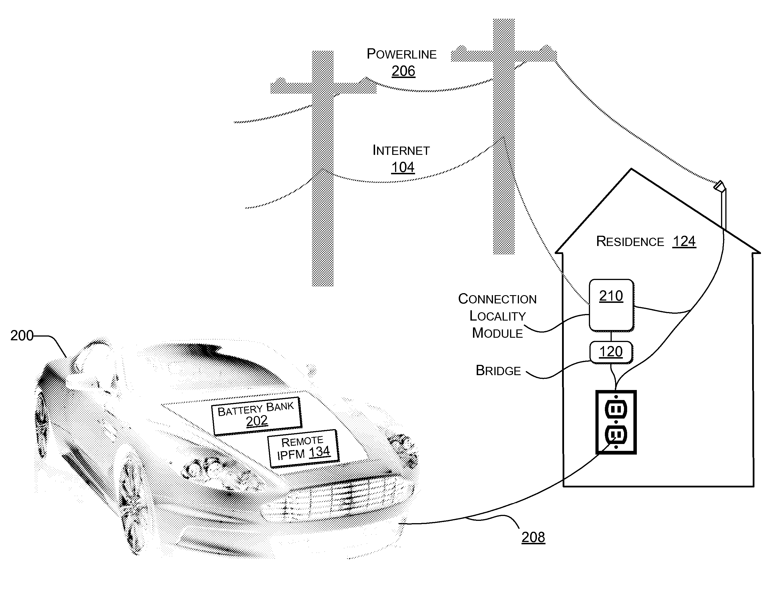
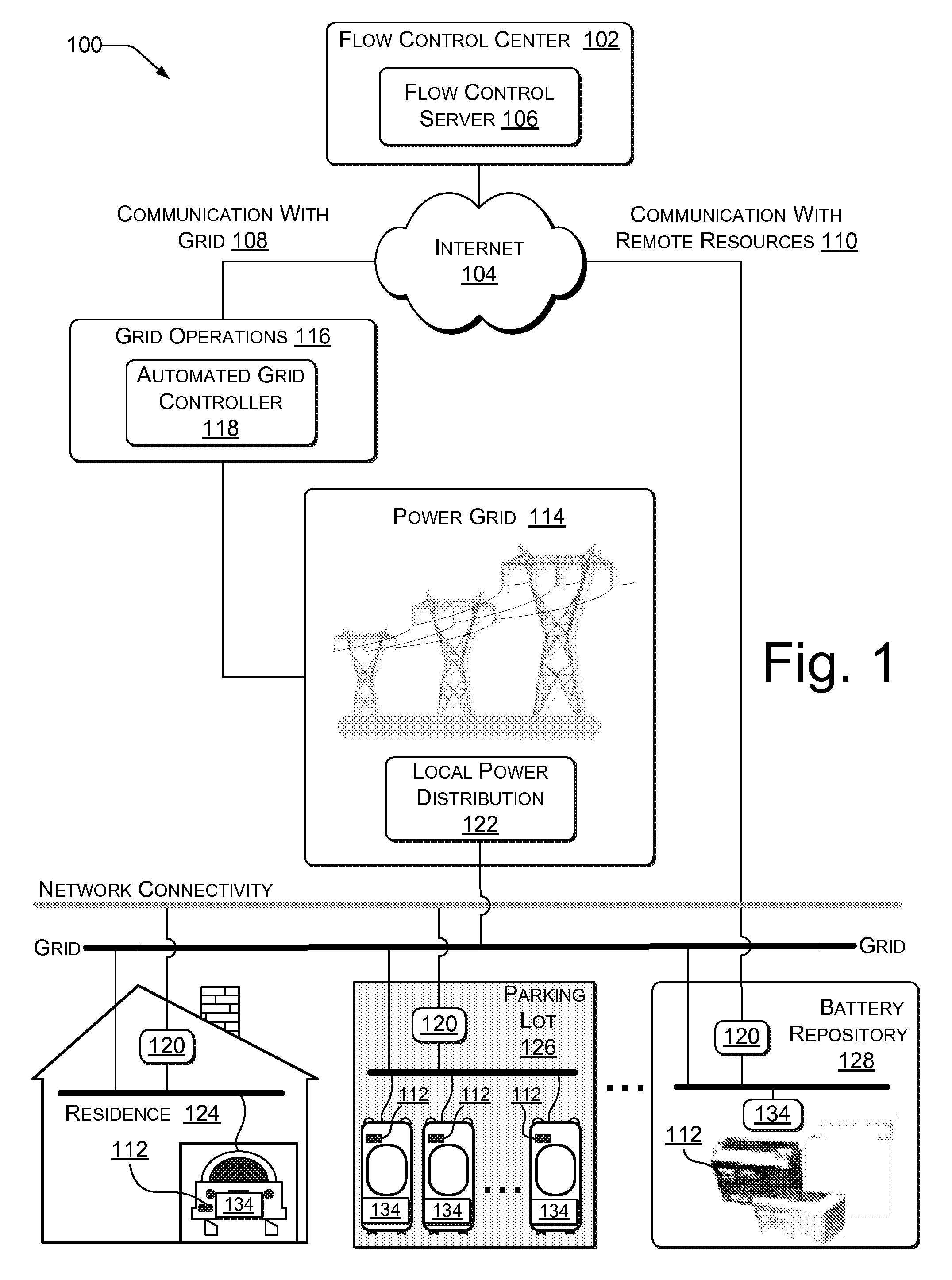
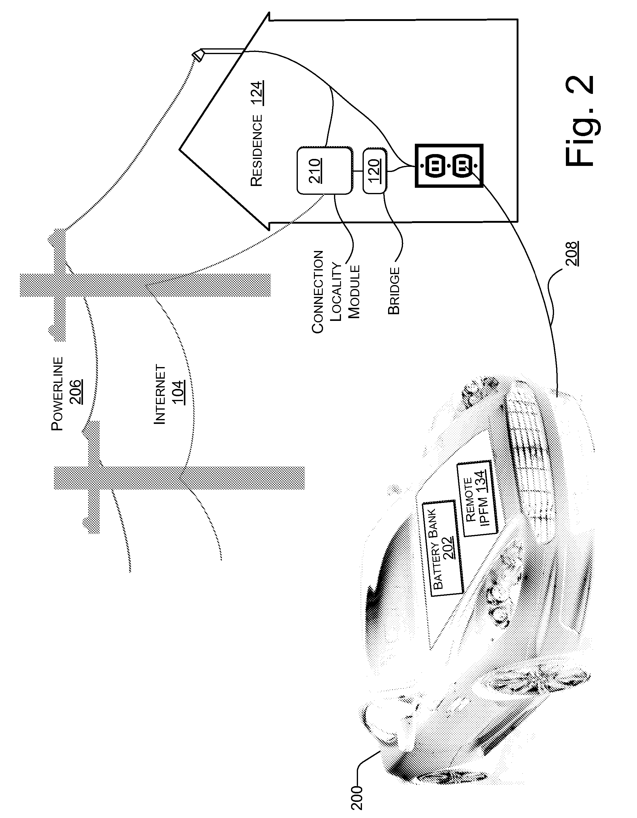
[0034]Overview

[0035]Described herein is a power aggregation system for distributed electric resources, and associated methods. In one implementation, the exemplary system communicates over the Internet and / or some other public or private networks with numerous individual electric resources connected to a power grid (hereinafter, “grid”). By communicating, the exemplary system can dynamically aggregate these electric resources to provide power services to grid operators (e.g. utilities, Independent System Operators (ISO), etc). “Power services” as used herein, refers to energy delivery as well as other ancillary services including demand response, regulation, spinning reserves, non-spinning reserves, energy imbalance, and similar products. “Aggregation” as used herein refers to the ability to control power flows into and out of a set of spatially distributed electric resources with the purpose of providing a power service of larger magnitude. “Power grid operator” as used herein, ref...


PUM


Abstract

Systems and methods are described for a power aggregation system. In one implementation, a service establishes individual Internet connections to numerous electric resources intermittently connected to the power grid, such as electric vehicles. The Internet connection may be made over the same wire that connects the resource to the power grid. The service optimizes power flows to suit the needs of each resource and each resource owner, while aggregating flows across numerous resources to suit the needs of the power grid. The service can bring vast numbers of electric vehicle batteries online as a new, dynamically aggregated power resource for the power grid. Electric vehicle owners can participate in an electricity trading economy regardless of where they plug into the power grid.

Description

RELATED APPLICATIONS[0001]This application claims priority to U.S. Provisional Patent Application No. 60 / 822,047 to David L. Kaplan, entitled, “Vehicle-to-Grid Power Flow Management System,” filed Aug. 10, 2006 and incorporated herein by reference; U.S. Provisional Patent Application No. 60 / 869,439 to Seth W. Bridges, David L. Kaplan, and Seth B. Pollack, entitled, “A Distributed Energy Storage Management System,” filed Dec. 11, 2006 and incorporated herein by reference; and U.S. Provisional Patent Application No. 60 / 915,347 to Seth Bridges, Seth Pollack, and David Kaplan, entitled, “Plug-In-Vehicle Management System,” filed May 1, 2007 and incorporated herein by reference.[0002]This application is also related to U.S. patent application Ser. No. 11 / 836,741, entitled, “Power Aggregation System for Distributed Electric Resources” by Kaplan et al., filed concurrently on Aug. 9, 2007, and incorporated herein by reference; to U.S. patent application Ser. No. 11 / 836,743, entitled, “Elect...

Claims


Application Information

Patent Timeline
Patent Type & Authority Patents(United States)
IPC IPC(8): G05D17/00G05D3/00G01R11/56G06Q40/00B60Q1/26
CPCB60L11/1811B60L11/1842G06Q40/04G06Q50/06B60L11/184Y02T90/121B60L2230/34B60L2240/622B60L2270/34Y02E60/721Y02T10/7005Y02T10/7088Y02T10/7291Y02T90/127Y02T90/128Y02T90/14Y02T90/16Y02T90/162Y02T90/163Y04S10/126Y02T90/169Y04S30/14Y04S10/58Y04S50/00Y04S50/16B60L53/20B60L53/64B60L55/00B60L53/57Y02E60/00Y02T10/7072Y02T10/72Y02T10/70Y02T90/12Y02T90/167Y04S10/50
Inventor POLLACK, SETH B.BRIDGES, SETH W.KAPLAN, DAVID L.
Owner GRIDPOINT
Why Eureka
Try Eureka