Assembly of abutting vacuum insulated panels arranged to form a retention chamber with a slip surface interposed between the panels

Active Publication Date: 2011-05-31
PELI BIOTHERMAL LLC
View PDF73 Cites 40 Cited by
  • Summary
  • Abstract
  • Description
  • Claims
  • Application Information

AI Technical Summary

Benefits of technology

[0003]The invention is an assembly of abutting vacuum insulated panels configured and arranged to form a retention chamber wherein a slip surface

Problems solved by technology

Goods such as medical supplies, blood, and vaccines are often extremely temperature sensitive and need to be maintained within a given temperature range.
Transport is particularly challenging.
However, once the external

Method used


Image

  • Assembly of abutting vacuum insulated panels arranged to form a retention chamber with a slip surface interposed between the panels
  • Assembly of abutting vacuum insulated panels arranged to form a retention chamber with a slip surface interposed between the panels
  • Assembly of abutting vacuum insulated panels arranged to form a retention chamber with a slip surface interposed between the panels

Examples


Example

Nomenclature

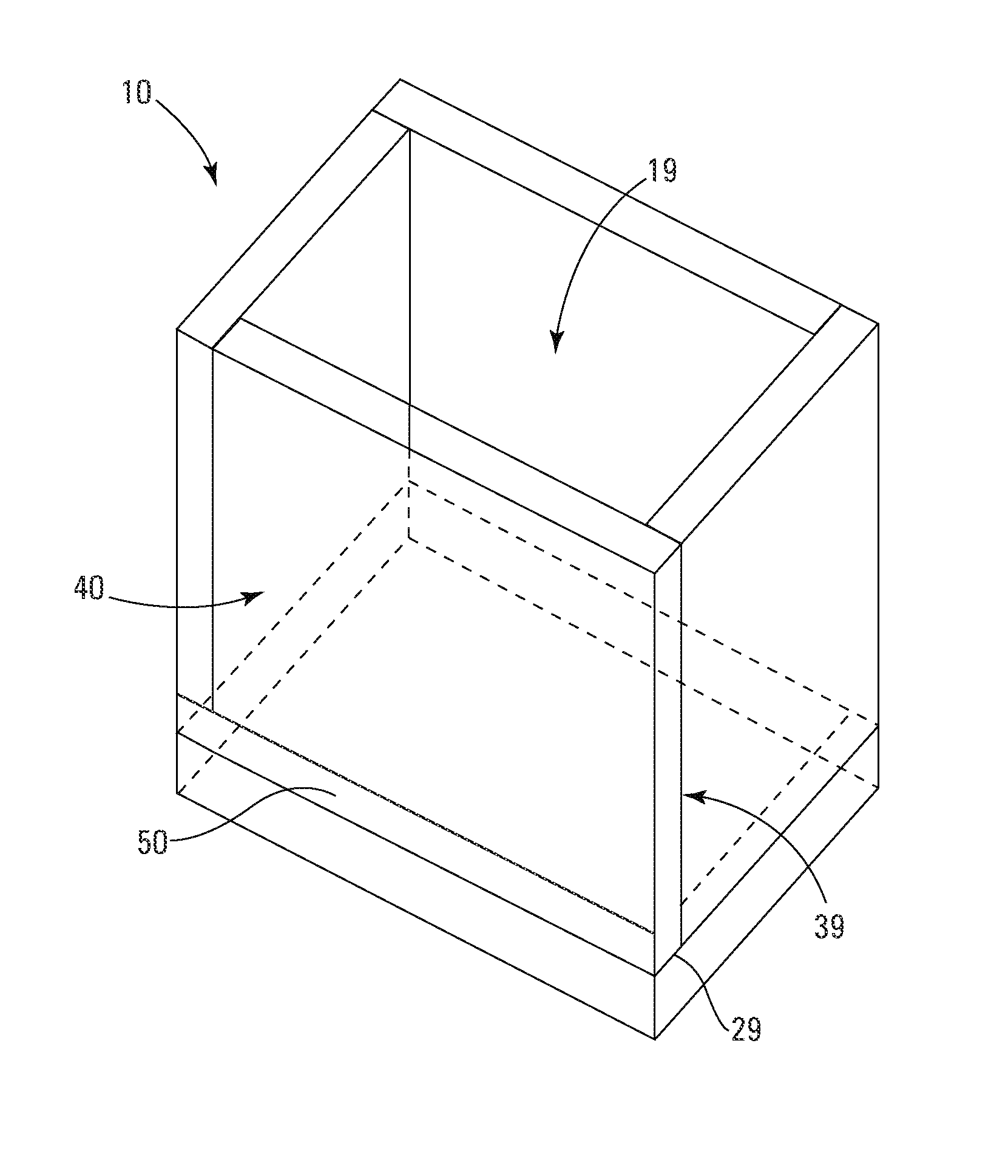
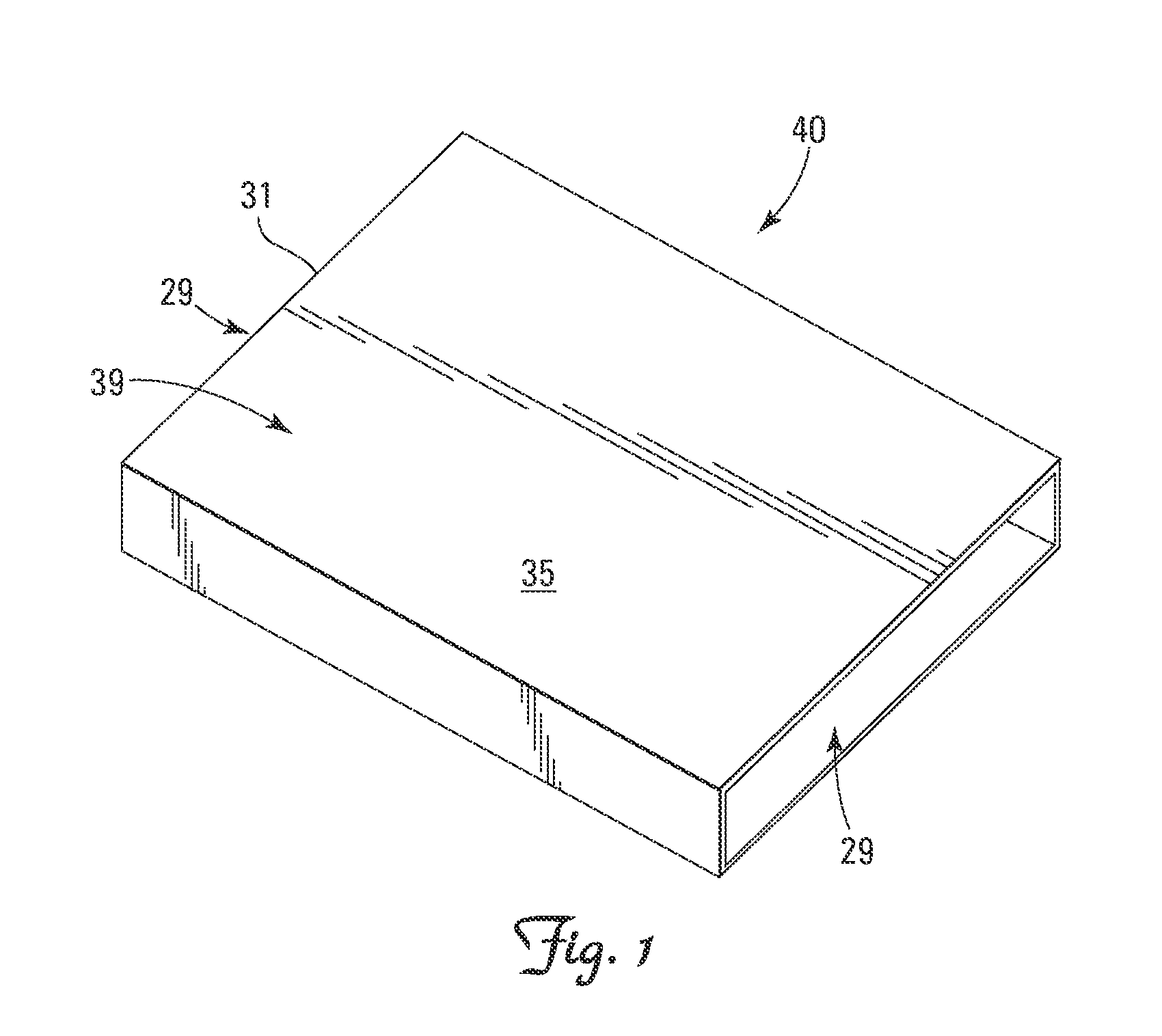
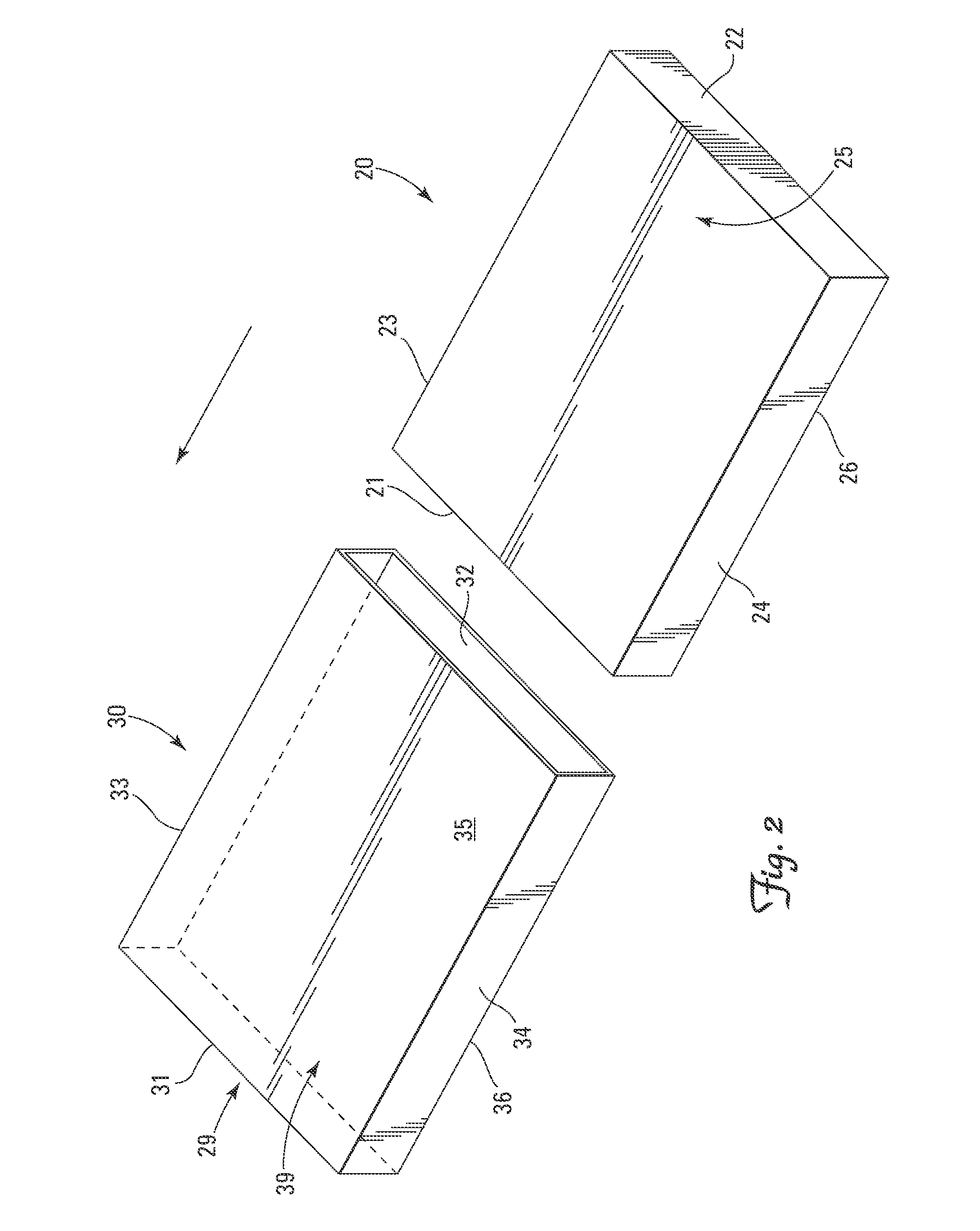
[0009]10 Container[0010]19 Retention Chamber[0011]20 Vacuum Insulated Panel[0012]20i Open Cell Foam Core of VIP[0013]20o Gastight Outer Film of VIP[0014]21 Top Edge of Vacuum Insulated Panel[0015]22 Bottom Edge of Vacuum Insulated Panel[0016]23 Right Edge of the Panel[0017]24 Left Edge of the Panel[0018]25 First Major Surface of the Panel[0019]26 Second Major Surface of the Panel[0020]29 Abutment Area[0021]30 Protective Sleeve[0022]31 Top Edge of the Protective Sleeve[0023]32 Bottom Edge of the Protective Sleeve[0024]33 Right Edge of the Protective Sleeve[0025]34 Left Edge of the Protective Sleeve[0026]35 First Major Surface of the Protective Sleeve[0027]36 Second Major Surface of the Protective Sleeve[0028]39 Slip Surface Provided by the Protective Sleeve[0029]40 Wear-Protected Insulating Panel[0030]50 Adhesive Tape

[0031]We have discovered that the useful life of a vacuum insulated panel 20 can be significantly increased by reducing abrasive wear of the airtight outer f...


PUM


Abstract

The invention is an assembly of abutting vacuum insulated panels configured and arranged to form a retention chamber with a slip surface providing a low kinetic coefficient of friction interposed between the panels within the abutment areas.

Description

BACKGROUND[0001]Goods such as medical supplies, blood, and vaccines are often extremely temperature sensitive and need to be maintained within a given temperature range. Transport is particularly challenging. Such temperature sensitive goods are shipped to a variety of destinations where the ambient outside temperature varies from extreme cold to extreme heat.[0002]In the prior art, shipment of temperature controlled supplies has been at least partially achieved by shipping containers lined with six separate vacuum insulation panels forming a container for the temperature sensitive goods. Vacuum insulated panels are extremely effective insulators as long as the internal vacuum remains intact. However, once the external barrier of the panels is breached and the vacuum ceases to exist, the thermal performance of the panels is reduced. The gas resistant outer film of the panel which seals the internal vacuum provides little protection. Therefore, a need exists for an assembly of vacuum...

Claims


Application Information

Patent Timeline
IPC IPC(8): F25D3/08
CPCF25D23/063B65D81/3813F25D2201/14
Inventor MAYER, WILLIAM N.MAYER, WILLIAM T.MANKELL, KURT O.
Owner PELI BIOTHERMAL LLC
Why Eureka
Try Eureka