High pressure common rail fuel system with gas injection

a fuel system and high pressure technology, applied in liquid fuel feeders, machines/engines, mechanical equipment, etc., can solve the problems of cavitation, production of cavitation, and high temperature spots, and achieve the effect of reducing cavitation

Active Publication Date: 2011-05-31
CUMMINS INC
View PDF47 Cites 16 Cited by
  • Summary
  • Abstract
  • Description
  • Claims
  • Application Information

AI Technical Summary

Benefits of technology

[0007]In accordance with another disclosed exemplary embodiment, a method of reducing cavitation in a high pressure common rail fuel system may include providing a fuel supply to a high pressure pump assembly, delivering a gas supply to the high pressure pump assembly, and mixing fuel and gas to form a gas fuel mixture. The mixture may be pressurized at a first pressure and the pressurized gas fuel mixture may be supplied to a common rail fuel system. The method may also include atomizing the gas fuel mixture at a second pressure below said first pressure.

Problems solved by technology

However, the injection system of Hankins et al. may generate undesirable effects within the fuel line or fuel system components as a result of fuel displacement within the injection system.
One undesirable effect may include the production of cavitation, i.e., the formation of microscopic bubbles dispersed throughout the fuel within the fuel injection system.
As a result, spots of high temperature are created and shock waves are emitted against surfaces in close proximity.
The effects of cavitation can cause damage or failure to components within the fuel injection system and reduce the service life of fuel injection equipment.
Additionally, damage due to cavitation may alter the flow characteristics of control orifices within the fueling system and even the injector nozzle orifices which may result in altering the fuel mixture and / or emissions characteristics of the fuel system over time.

Method used


Image

  • High pressure common rail fuel system with gas injection
  • High pressure common rail fuel system with gas injection
  • High pressure common rail fuel system with gas injection

Examples


Embodiment Construction

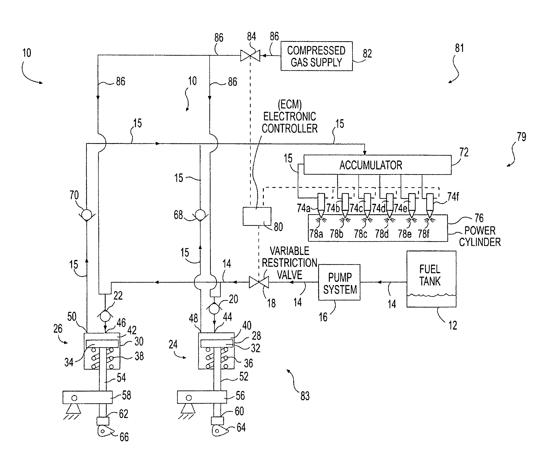
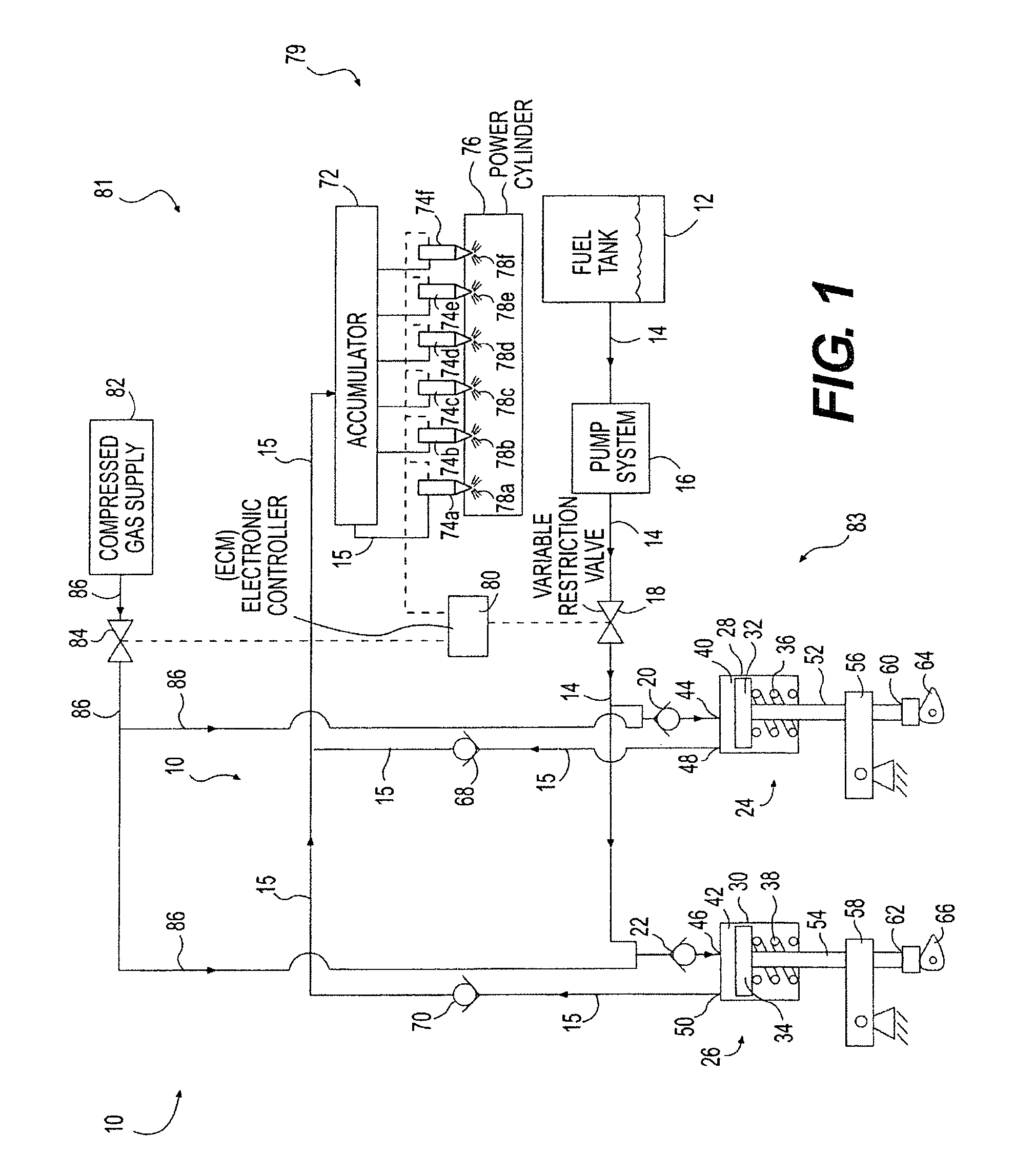
[0012]Referring to FIG. 1, the enhanced high pressure common rail fuel system 10 of the present invention supplies fuel to one or more power cylinders 76 of a power source. The power source may include an engine such as, for example, a diesel engine, a gasoline engine, a natural gas engine, or any other engine apparent to one skilled in the art. The power source may perform a combustion process which may be configured to utilize, for example, an air / fuel mixture. The power source may, alternatively, include another source of power such as a furnace or any other source of power known in the art.

[0013]The enhanced high pressure common rail fuel system 10 includes a common rail fuel system 79, a gas supply system 81, and a high pressure pump assembly 83. A fuel tank 12 is fluidly connected to the high pressure common rail fuel system 10 to provide a combustible substance via supply lines 14. The combustible substance may include, for example, gasoline, diesel fuel, reformate, and / or an...


PUM


Abstract

A high pressure common rail fuel system is provided including a fuel supply, a high pressure pump assembly fluidly connected to receive fuel from the fuel supply, and a gas supply system fluidly connected to provide gas to the high pressure pump assembly to create a high pressure gas fuel mixture. A common rail fuel system is fluidly connected to the high pressure pump assembly to receive the high pressure gas fuel mixture.

Description

TECHNICAL FIELD[0001]The invention relates generally to an improved high pressure common rail fuel system and, more particularly, to a fuel system for controlling cavitation and improving dispersion of fuel.BACKGROUND OF THE INVENTION[0002]With the advent of increased fuel economy and reduced emissions requirements imposed by the government, various fuel systems have been developed to precisely control the amount of fuel that is injected during the injection events of a combustion cycle. In particular, high pressure fuel injection systems have been developed which provide increased control of the fuel injected by the fuel injectors of an internal combustion engine in comparison to conventional fuel injection systems.[0003]Such high pressure fuel injection systems typically utilize at least one high pressure pump that pressurizes the fuel to be injected by the fuel injectors. Fuel systems may utilize a plurality of such pressure pumps corresponding to the number of fuel injectors, ea...

Claims


Application Information

Patent Timeline
Patent Type & Authority Patents(United States)
IPC IPC(8): F02M69/46
CPCF02D19/0605F02D19/0684F02M43/00F02D19/081F02M67/005F02D19/0623F02D19/0642F02D19/0694F02M63/0225F02B3/06F02D19/08Y02T10/36Y02T10/30
Inventor LUCAS, MICHAEL A.TEGNELIUS, LARSBENSON, DONALD J.
Owner CUMMINS INC
Why Eureka
Try Eureka