Electrically driven wheel and vehicle

a technology of electric drive and wheel, which is applied in the direction of electric propulsion mounting, mechanical equipment, transportation and packaging, etc., can solve the problems of increasing the size of the unit, the vehicle may move, etc., and achieve the effect of simple structure and reliable locking of the wheel

Inactive Publication Date: 2011-05-31
TOYOTA JIDOSHA KK +1
View PDF22 Cites 12 Cited by
  • Summary
  • Abstract
  • Description
  • Claims
  • Application Information

AI Technical Summary

Benefits of technology

[0007]One object of the present invention is to provide an electrically driven wheel and a vehicle having a parking lock mechanism capable of locking a wheel reliably with a simple structure.
[0009]With the above arrangement, since the parking lock mechanism is provided separately from the brake mechanism, the parking lock mechanism can lock the wheel reliably. Further, since the parking lock mechanism is provided in the in-wheel motor, an increase in the size of a unit can be suppressed.
[0011]With the above arrangement, the parking lock mechanism can lock the wheel reliably while suppressing an increase in the size of a unit.
[0013]With the above arrangement, a relatively large friction area can be obtained, and thus the wheel can be locked reliably by the parking lock mechanism with a simple structure.
[0015]With the above arrangement, a parking lock mechanism capable of locking a wheel reliably while suppressing an increase in the size of a unit can be obtained.
[0019]According to the present invention, an electrically driven wheel having a parking lock mechanism capable of locking a wheel reliably with a simple structure can be provided as described above.

Problems solved by technology

However, when a brake mechanism used while a vehicle is moving and a parking brake mechanism are integrated as described in Japanese Patent Laying-Open No. 2002-104160, the vehicle may move when a brake failure occurs.
On the other hand, using a disc brake as a parking lock mechanism leads to an increase in the size of a unit.

Method used


Image

  • Electrically driven wheel and vehicle
  • Electrically driven wheel and vehicle
  • Electrically driven wheel and vehicle

Examples


case 410

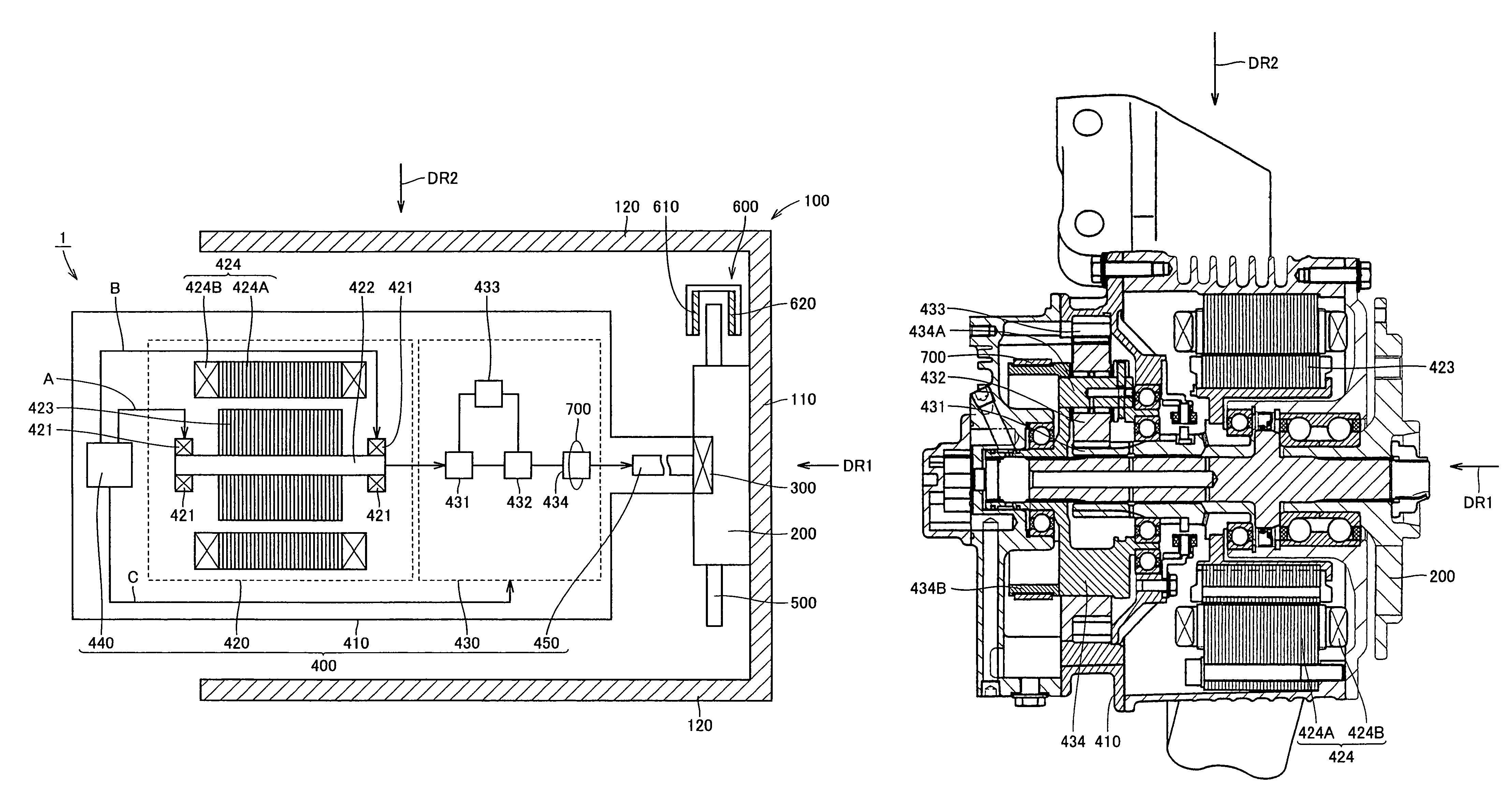
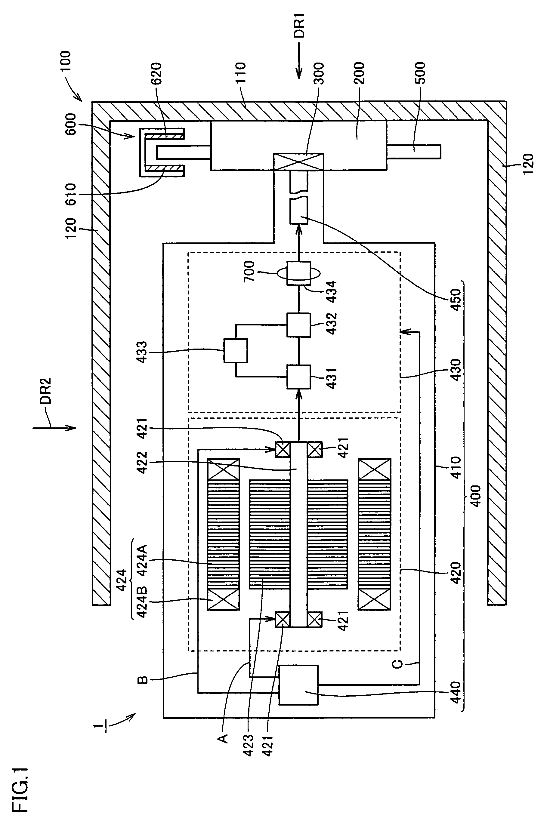
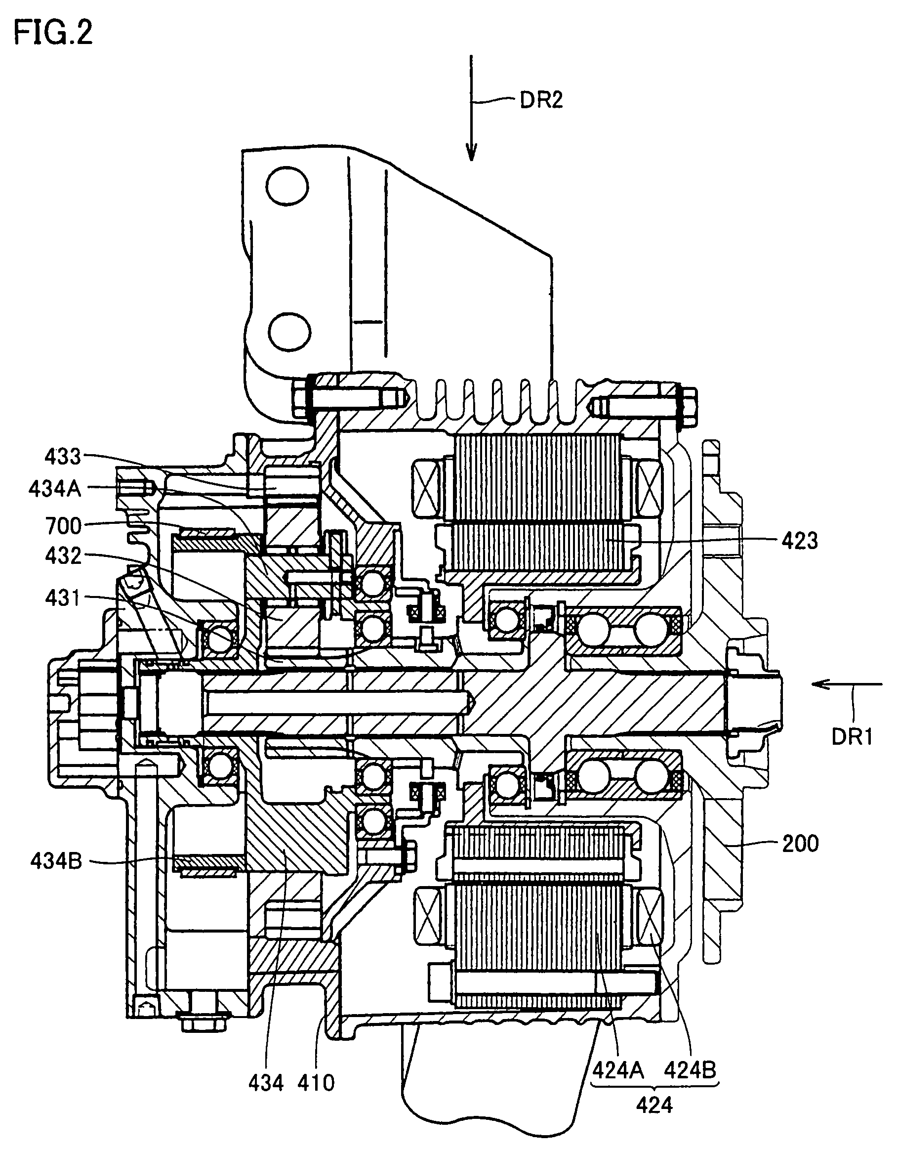
[0033]Case 410 is disposed on the left side of wheel hub 200 in the drawing, accommodating motor 420, planetary gear 430, oil pump 440, shaft 450, and an oil channel.

[0034]Motor 420 has a bearing 421, a rotary shaft 422, a rotor 423, and a stator 424. Stator 424 includes a stator core 424A and a stator coil 424B. Stator core 424A is fixed to case 410. Stator coil 424B is wound on stator core 424A. When motor 420 is a three-phase motor, stator coil 424B is formed of a U-phase coil, a V-phase coil, and a W-phase coil. Rotor 423 is disposed on the inner peripheral side of stator core 424A and stator coil 424B.

[0035]Planetary gear 430 includes a sun gear 431, a pinion gear 432, a ring gear 433, and a planetary carrier 434.

[0036]A sun gear shaft (not shown) is coupled to rotary shaft 422 of motor 420. Further, the sun gear shaft is rotatably supported. Sun gear 431 is coupled to the sun gear shaft. Pinion gear 432 engages sun gear 431 and is rotatably supported. Ring gear 433 is fixed to...


PUM


Abstract

An electrically driven wheel includes a wheel disc and a wheel hub; an in-wheel motor mounted within the wheel disc to drive the wheel disc and the wheel hub or to be driven by the wheel disc and the wheel hub; a brake rotor and a brake caliper suppressing rotation of the wheel disc and the wheel hub while a vehicle is moving; and a parking lock mechanism provided in the in-wheel motor separately from a brake mechanism formed of the brake rotor and the brake caliper. The parking lock mechanism is a band-type brake frictionally engaging a planetary carrier serving as an “output portion” of a “reduction mechanism”.

Description

TECHNICAL FIELD[0001]The present invention relates to an electrically driven wheel and a vehicle, and more particularly, to an electrically driven wheel and a vehicle having a parking lock mechanism.BACKGROUND ART[0002]A parking brake to lock a wheel while a vehicle is in a parking state has conventionally been known.[0003]For example, Japanese Patent Laying-Open No. 2002-104160 discloses a brake unit used in a drive wheel of an electric car employing an in-wheel motor, in which a brake applied while the car is moving and a parking brake are integrated.[0004]Further, Japanese Patent Laying-Open No. 09-295561 discloses a parking lock unit for an automatic transmission.[0005]However, when a brake mechanism used while a vehicle is moving and a parking brake mechanism are integrated as described in Japanese Patent Laying-Open No. 2002-104160, the vehicle may move when a brake failure occurs.[0006]Further, from a viewpoint different from the above, an electrically driven wheel having an ...

Claims


Application Information

Patent Timeline
Patent Type & Authority Patents(United States)
IPC IPC(8): B60K7/00F16D65/28
CPCF16D55/02F16D65/14H02K7/102B60K7/0007B60K17/046H02K7/14F16D2121/14F16D2123/00H02K7/116F16D2121/02
Inventor MORIGUCHI, NAOKITSUCHIDA, MICHITAKAMIZUTANI, RYOJISAKURAI, JUNICHIROTOJIMA, YUKI
Owner TOYOTA JIDOSHA KK
Why Eureka
Try Eureka