Apparatus and method utilizing magnetic field

a magnetic field and apparatus technology, applied in the direction of generators/motors, instruments, therapy, etc., can solve the problems of significant discomfort, tens of devices can only be used intermittently, and all the devices currently available for producing therapeutic stimulation have drawbacks, etc., to achieve the effect of small and ligh

Inactive Publication Date: 2011-05-31
FERRO SOLUTIONS
View PDF21 Cites 91 Cited by
  • Summary
  • Abstract
  • Description
  • Claims
  • Application Information

AI Technical Summary

Benefits of technology

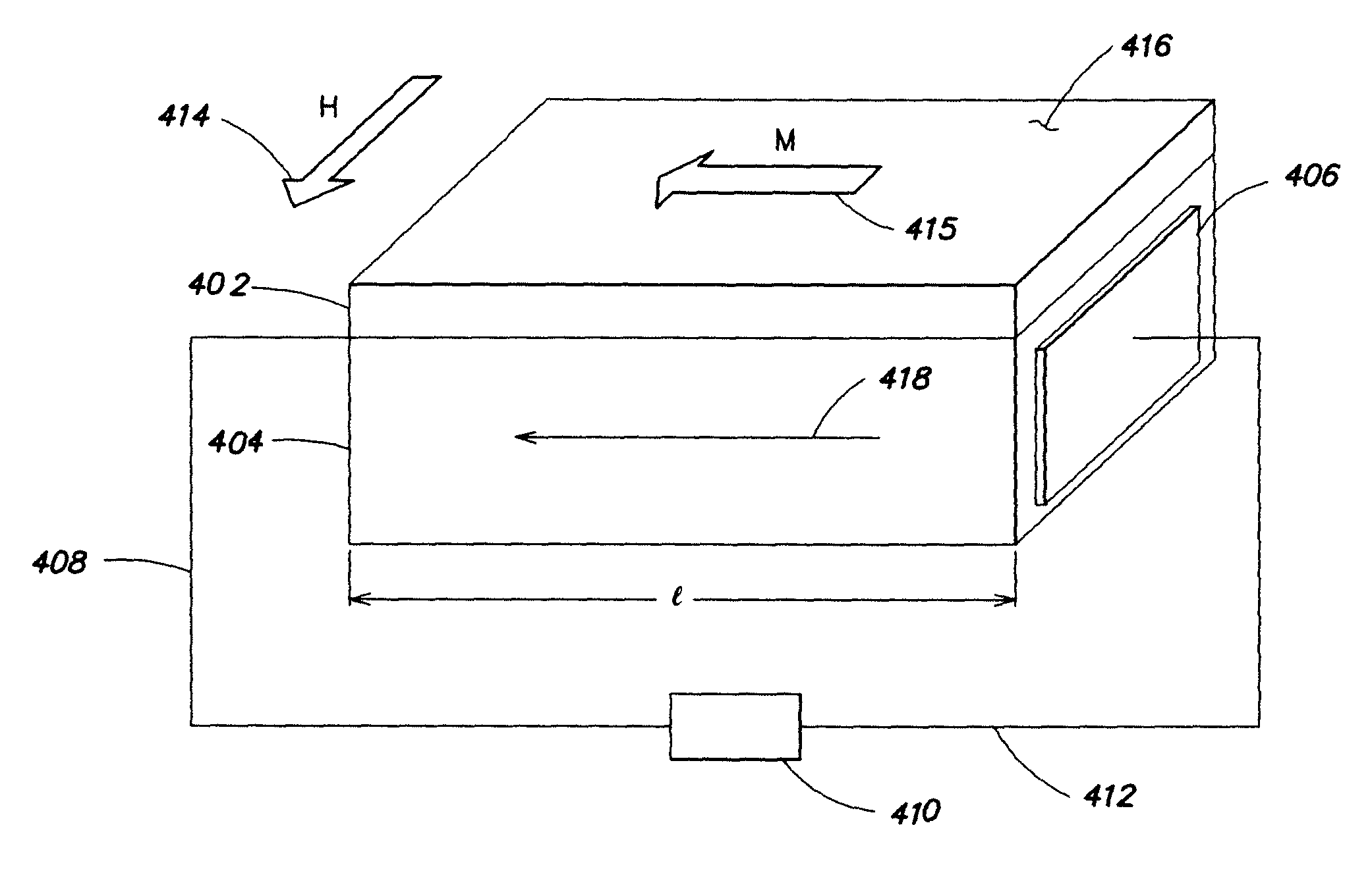
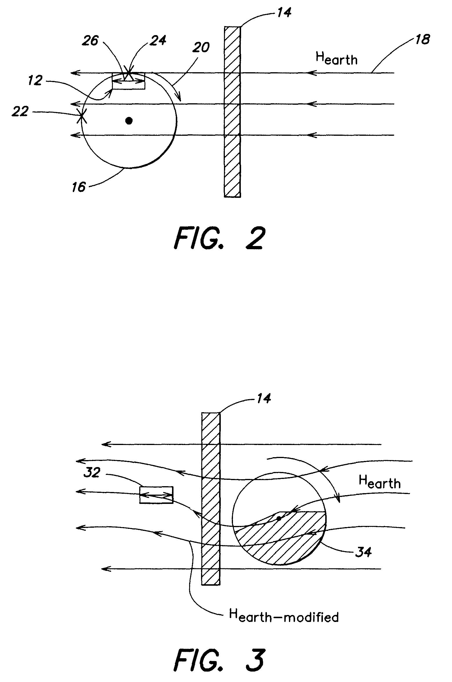
[0007]In accordance with various embodiments of the present invention, an apparatus is provided for harvesting energy from the environment or other remote sources and converting it to useful electrical energy. The harvester does not contain a permanent magnet or other local field source but instead relies on the earth's magnetic field or another source of a magnetic field that is external to the sensing device. One advantage of these new harvesters is that they can be made smaller and lighter than energy harvesters that contain a magnet. Another advantage is that they do not require vibrational energy to function.

Problems solved by technology

All of the devices currently available for producing therapeutic stimulation have drawbacks.
TENS devices can produce significant discomfort and can only be used intermittently.
These devices may only be used acutely, and may cause significant discomfort.
Implantable, chronic stimulation devices are available, but these currently require a significant surgical procedure for implantation.
The implantable devices are relatively large and expensive.
In addition, they require significant surgical procedures for placement of electrodes, leads, and processing units.
Drawbacks, such as size (of internal and / or external components), discomfort, inconvenience, complex surgical procedures, and / or only acute or intermittent use has generally confined their use to patients with severe symptoms and the capacity to finance the surgery.
The gate control theory has always been controversial, as there are certain conditions such as hyperalgesia, which it does not fully explain.
A damaged nerve may be sensitive to slight mechanical stimuli (motion) and / or noradrenaline (a chemical utilized by the sympathetic nervous system), which in turn results in abnormal firing of the nerve's pain fibers.
The negative with this therapy however is that the recharge capacity of these products is very poor, and that they do not have the capacity to deliver therapy for prolonged periods of time.

Method used


Image

  • Apparatus and method utilizing magnetic field
  • Apparatus and method utilizing magnetic field
  • Apparatus and method utilizing magnetic field

Examples


example of one embodiment

[0140]Consider a 3 cm-diameter, ten-turn coil with each turn (made from wire or a flat foil or film) having a cross section of 0.05×1 mm; it would have a resistance of less than 1 Ohm. When driven by a 10 Vrms AC signal (possibly battery-powered), it would draw a current of 20-30 A producing a field of order 100 Oe 1 or 2 cm beneath the coil. This is more than enough to produce a significant rotation in the magnetization of the PME sensor. The antenna will dissipate only a few Wafts while it is activated. The PME-33 sensor / harvester will generate several hundreds of Volts (depending on its size as well as the circuit and device it drives). The PME sensor is essentially a capacitor that has a value of C typically in the range of 0.1-10 nF. Thus the power stored on the capacitor under the action of a magnetic field alternating at the resonance frequency of the PME sensor, typically 10-30 kH for cm-scale devices) will be in the range of tens of Watts. The power that can be drawn from t...


PUM


Abstract

Apparatus and method for harvesting energy from the environment and / or other external sources and converting it to useful electrical energy. The harvester does not contain a permanent magnet or other local field source but instead relies on the earth's magnetic field of another source of a magnetic field that is external to the sensing device. One advantage of these new harvesters is that they can be made smaller and lighter than energy harvesters that contain a magnet and / or an inertial mass.

Description

RELATED APPLICATIONS[0001]This application claims the benefit of priority to U.S. Provisional Application No. 60 / 791,004, filed Apr. 11, 2006, and is a continuation-in-part of U.S. application Ser. No. 11 / 652,272, filed Jan. 11, 2007, which claims the benefit of priority to U.S. Provisional Application No. 60 / 758,042, filed Jan. 11, 2006, and U.S. Provisional Application No. 60 / 790,921, filed Apr. 11, 2006, and is a continuation-in-part of U.S. application Ser. No. 10 / 730,355, filed Dec. 8, 2003, which claims the benefit of priority to U.S. Provisional Application No. 60 / 431,487, filed Dec. 9, 2002, the disclosures of which are incorporated herein by reference in their entirety.FIELD OF THE INVENTION[0002]This invention relates to apparatus and methods for harvesting energy from the environment and other sources external to the harvester and converting it to useful electrical energy. The present invention generally relates to implantable stimulator systems and methods, and more part...

Claims


Application Information

Patent Timeline
Patent Type & Authority Patents(United States)
IPC IPC(8): G01R33/02G01R29/22
CPCA61N1/3787A61N2/006H02N11/002H01L41/00H02K57/003G01R33/18A61N1/3785H02K99/10H10N35/00H10N30/00
Inventor HUANG, JIANKANGSUNDRAM, HARIHARAN VENKETESHO'HANDLEY, ROBERT C.BONO, DAVID C.
Owner FERRO SOLUTIONS
Why Eureka
Try Eureka