Exhaust cleaner for internal combustion engine

a technology for exhaust cleaners and internal combustion engines, which is applied in the direction of exhaust treatment electric control, machines/engines, separation processes, etc., can solve the problems of difficult to completely oxidize and remove pm emitted from engines, air contamination, and deterioration of fuel consumption, so as to reduce the temperature

Inactive Publication Date: 2011-06-07
TOYOTA JIDOSHA KK
View PDF24 Cites 23 Cited by
  • Summary
  • Abstract
  • Description
  • Claims
  • Application Information

AI Technical Summary

Benefits of technology

[0008]According to the exhaust purifying system for the internal combustion engine, since the ratio of the supply amount of the exhaust gas between said plurality of particulate matter collecting devices is adapted to be changed, the particulate matter collecting device can restrict consumption of the ozone by a certain substance in the exhaust gas, such as NOx or HC and restrict decomposition of the ozone due to heat of the exhaust gas in a particulate matter collecting device where the ratio of the supply amount in the exhaust gas is made small. In consequence, the ozone is efficiently usable, making it possible to improve a purification efficiency of PM by the ozone.
[0022]According to this aspect of the present invention, the filter chamber into which the ozone is supplied by the ozone supplying means can be closed by the valve means to restrict inflow of the exhaust gas into the filter chamber. Accordingly, it is prevented that the supplied ozone is wastefully consumed by the NOx in the exhaust gas or the like and therefore, a greater amount of the ozone can be used for oxidation and removal of PM deposited in the filter member. Therefore, the ozone can be efficiently used. In this case, it is preferable that said plurality of filter chambers are two chambers, one formed in the central portion and another in an outer peripheral portion inside said casing.
[0025]It is preferable that the system of the present invention is provided with at least one temperature detecting means for detecting a temperature of the gas entering into at least one of said filter members or a temperature of the one of the filter members and means for controlling the ozone supply from said ozone supplying means corresponding to the filter member based upon the detected temperature. In a case of oxidizing and removing PM in the filter member due to ozone, it is preferable to oxidize and remove PM when a temperature of the gas entering into the filter member or a temperature of the filter member is within such an appropriate temperature range that the PM oxidation due to the ozone can be effectively performed. According to the preferred aspect, the ozone supply can be performed only when the detected temperature is within the appropriate temperature range, preventing the supplied ozone from being wastefully consumed in an inappropriate temperature range.
[0026]It is preferable that in this case the system is provided with cooling gas supplying means disposed between at least one of said filter members and said valve means for supplying a cooling gas to the filter member from the upstream side thereof, and means for controlling the cooling gas supply from the cooling gas supplying means in accordance with the detected temperature. According to this preferred aspect, in a case where a temperature in accordance with the filter member performing PM oxidation and removal is higher than the appropriate temperature range, supply of the cooling air is performed from the air supplying means, making it possible to reduce the temperature to the appropriate temperature range. In consequence, the ozone supply can be performed within the appropriate temperature range, preventing the supplied ozone from being wastefully consumed in an inappropriate temperature range.

Problems solved by technology

There is generally known that exhaust gas in a diesel engine contains particulate matter (hereinafter, referred to as “PM”) including carbon as a major constituent, which is the cause of air contamination.
However, the proposed methods have the following problems.
The method of forcibly injecting and supplying fuel has the problem of inviting deterioration of fuel consumption and also damages of the DPF caused by a temperature rise as a result of rapid combustion of PM, the method described in Japanese Patent Laid-Open No. 2002-531762 has the problem that due to slowness of an oxidizing speed of PM by NO2, it is difficult to completely oxidize and remove PM emitted from an engine, and the method of using DPF with a catalyst described in Japanese Patent Laid-Open No. 06-272541 or Japanese Patent Laid-Open No. 09-125931 has the problem that since the catalyst and PM both are solid substances, both do not sufficiently contact, causing an insufficient oxidative reaction of the PM.
However, since the method described in Japanese Patent Laid-Open No. 2005-502823 is adapted to generate ozone from oxygen as a constituent in exhaust gas by plasma and introduce the generated ozone as well as the exhaust gas containing NOx and the like into a particulate filter, a generation amount of ozone is not sufficient and ozone having a strong oxidation effect possibly reacts with and is consumed in the NOx and the like in the exhaust gas before entering into the particulate filter.
Therefore, there is a problem that an amount of ozone usable for oxidation and removal of PM is reduced and a sufficient purification efficiency can not be obtained, thereby possibly deteriorating an oxidation speed of PM.

Method used


Image

  • Exhaust cleaner for internal combustion engine
  • Exhaust cleaner for internal combustion engine
  • Exhaust cleaner for internal combustion engine

Examples


first embodiment

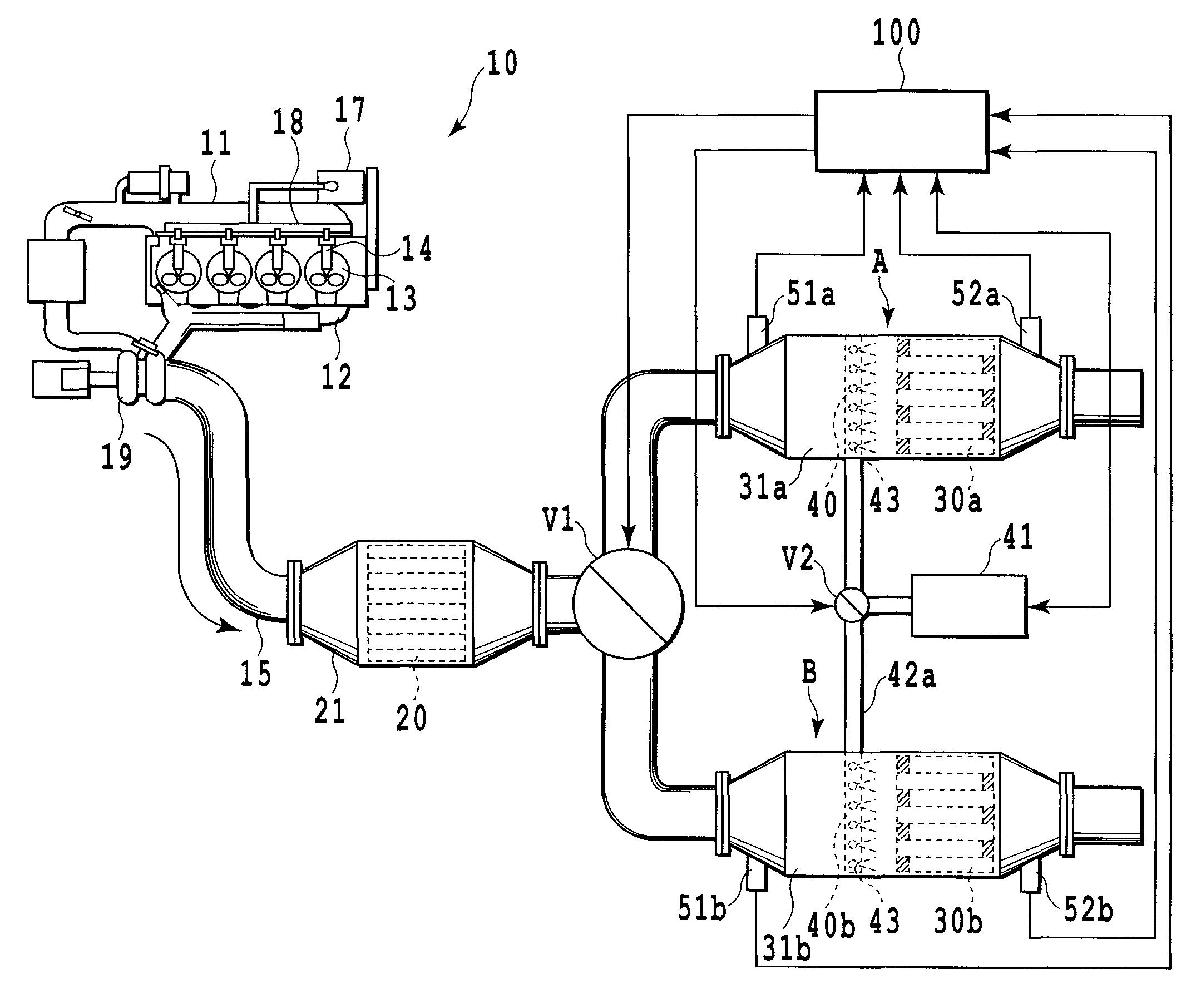
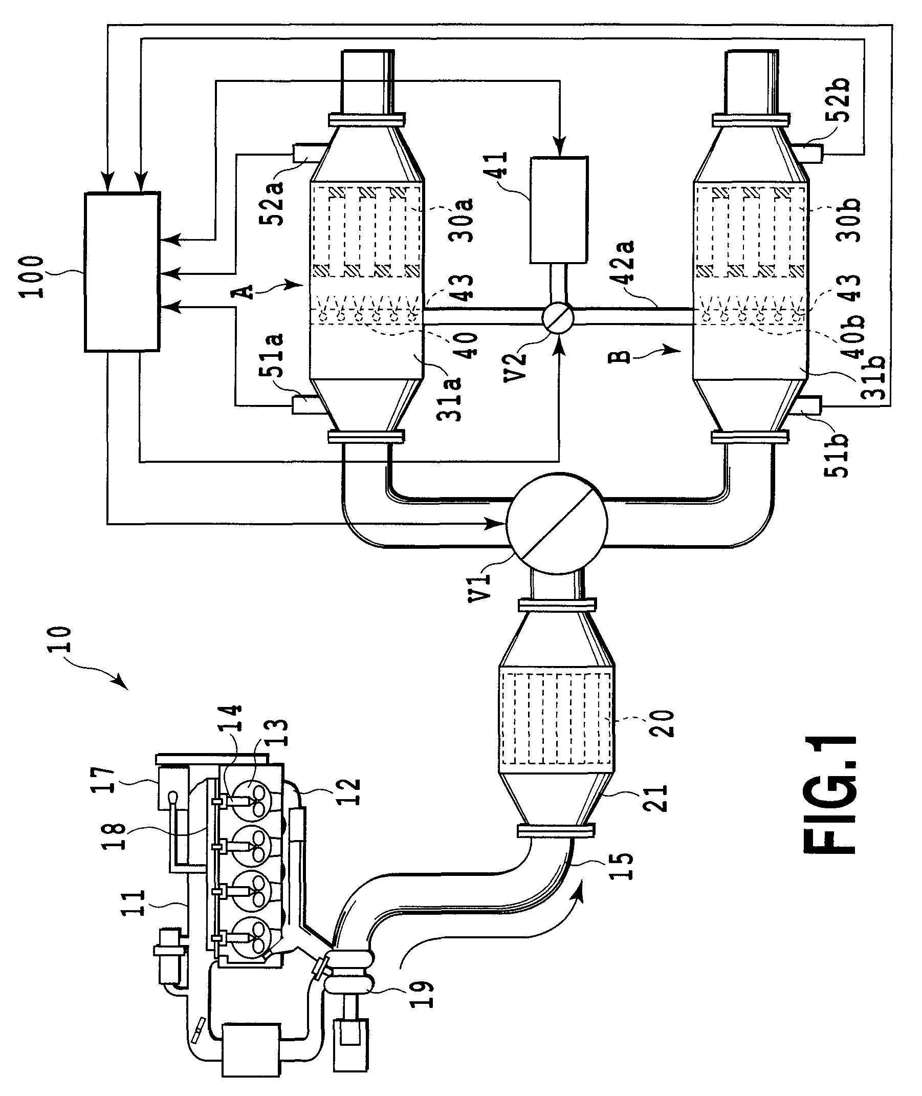
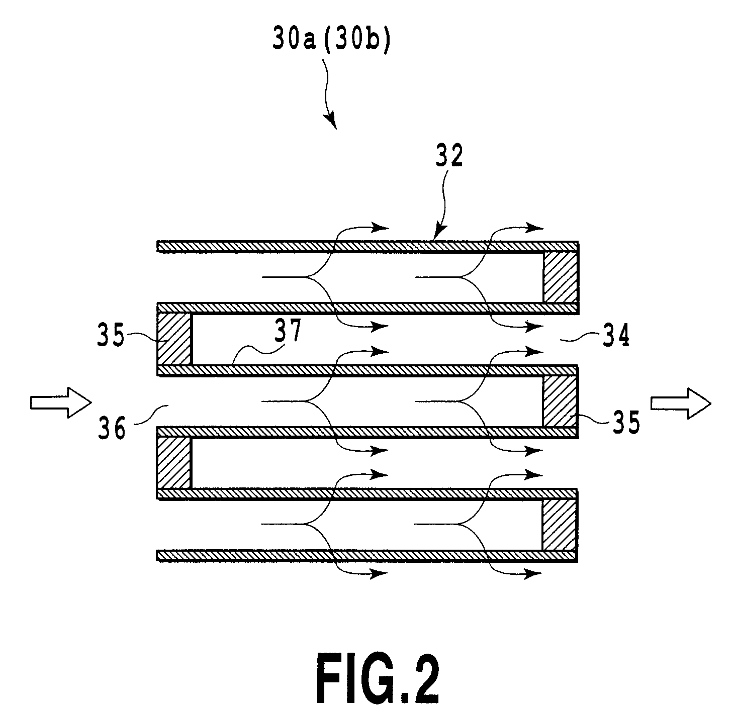
[0057]FIG. 1 is a system diagram schematically showing an exhaust purifying system for an internal combustion engine in a first embodiment of the present invention. In the figure, numeral 10 denotes a compression ignition type internal combustion engine, i.e., a diesel engine, numeral 11 denotes an intake manifold communicated to intake ports, numeral 12 denotes an exhaust manifold communicated to exhaust ports and numeral 13 denotes a combustion chamber. In the present embodiment, fuel supplied to a high-pressure pump 17 from a fuel tank (not shown) is supplied under pressure to a common rail 18 by the high-pressure pump 17 and accumulated therein in a high-pressure state and the high-pressure fuel in the common rail 18 is directly injected and supplied into the combustion chamber 13 from a fuel injection valve 14. Exhaust gas from the diesel engine 1 flows from the exhaust manifold 12 to a turbocharger 19 and thereafter, flows into a exhaust passage 15 at the downstream side there...

second embodiment

[0104]Next, a second embodiment of the present invention will be explained with the accompanying drawings. FIG. 8 is a system diagram schematically showing an exhaust purifying system for an internal combustion engine in a second embodiment of the present invention. As illustrated, the second embodiment is provided with means for detecting a DPF floor temperature of each of DPFs 30a and 30b. That is, the DPFs 30a and 30b are respectively provided with temperature sensors 53a and 53b disposed therein and ECU 100 individually calculates the floor temperature of each of DPFs 30a and 30b based upon detection signals of the temperature sensors 53a and 53b. A temperature detecting section (in a case of a thermocouple, the tip) of each of the temperature sensors 53a and 53b is buried inside each of the DPFs 30a and 30b for detecting the floor temperature of each of DPFs 30a and 30b, but the temperature detecting section of each of the temperature sensors 53a and 53b may be disposed near th...

third embodiment

[0118]Next, the third embodiment of the present invention will be explained with the accompanying drawings. FIG. 11 is a system diagram schematically showing an exhaust purifying system for an internal combustion engine in the third embodiment of the present invention. As illustrated, the third embodiment is provided with means for detecting DPF floor temperature of each of DPFs 30a and 30b. That is, the DPFs 30a and 30b are respectively provided with temperature sensors 53a and 53b disposed therein and ECU 100 individually calculates the floor temperature of each of DPFs 30a and 30b based upon detection signals of the temperature sensors 53a and 53b. A temperature detecting section (in a case of a thermocouple, the tip) of each of the temperature sensors 53a and 53b is buried inside each of the DPFs 30a and 30b for detecting the floor temperature of each of DPFs 30a and 30b, but the temperature detecting section of each of the temperature sensors 53a and 53b may be disposed near th...


PUM

PropertyMeasurementUnit
lengthaaaaaaaaaa
diameteraaaaaaaaaa
temperatureaaaaaaaaaa

Abstract

An exhaust purifying system for an internal combustion engine is provided with a plurality of DPFs (30a and 30b) branched and connected to an exhaust passage (15) for collecting particulate matter in an exhaust gas and an ozone supplier for supplying ozone to the upstream side of each of the plurality of DPFs (30a and 30b). The system respectively changes a ratio of a supply amount of the exhaust gas and a ratio of a supply amount of the ozone between the plurality of DPFs (30a and 30b).

Description

TECHNICAL FIELD[0001]The present invention relates to an exhaust purifying system for an internal combustion engine and in particular, to an exhaust purifying system for an internal combustion engine which collects and oxidizes particulate matter in exhaust gas emitted from a diesel engine for purifying it.BACKGROUND ART[0002]There is generally known that exhaust gas in a diesel engine contains particulate matter (hereinafter, referred to as “PM”) including carbon as a major constituent, which is the cause of air contamination. Therefore, there are proposed various systems and methods for trapping and removing the PM from the exhaust gas.[0003]For example, there are proposed methods such as a method that fuel is forcibly injected and supplied to increase a temperature of a diesel particulate filter (DPF) for oxidizing and burning the collected PM, a method that nitrogen dioxide NO2 is generated from nitrogen monoxide NO in exhaust gas and PM is oxidized by NO2 (for example, Japanese...

Claims


Application Information

Patent Timeline
Patent Type & Authority Patents(United States)
IPC IPC(8): F01N3/00
CPCB01D53/944F01N13/011F01N3/029F01N3/031F01N9/002F01N11/002F01N13/017F01N13/0093F01N13/009B01D2258/012F01N3/0807F01N3/206F01N2240/38F01N2550/12F02B37/00Y02T10/47B01D2251/104Y02T10/40B01D53/94F01N3/02F01N3/08F01N3/24
Inventor HIRATA, HIROHITOKAKINOHANA, MASARUIBE, MASAYA
Owner TOYOTA JIDOSHA KK
Why Eureka
Try Eureka