Image acquisition apparatus and image acquisition method using optical coherence tomography

a technology of optical coherence tomography and image acquisition apparatus, which is applied in the field of image acquisition apparatuses and image acquisition methods, can solve the problems of difficult high-speed scanning, inability to efficiently weight the diagnostic importance of the area, and inability to use high-speed resonant scanners in either of the two-dimensional axes

Inactive Publication Date: 2011-06-07
CANON KK
View PDF2 Cites 21 Cited by
  • Summary
  • Abstract
  • Description
  • Claims
  • Application Information

AI Technical Summary

Benefits of technology

[0012]The present invention provides an image acquisition apparatus that uses OCT, which allows for weighting above scan lines with respect to an area of importance that is to become an examined subject of an examination object.
[0013]An image acquisition apparatus that uses optical coherence tomography according to an aspect of the present invention is configured to split light from a light source into signal light and reference light, guide the signal light to an examination object and the reference light to a reference mirror, and acquire a tomographic image of the examination object by using return light obtained as a result of the signal light reflected or diffused by the examination object and the reference light reflected by the reference mirror. The image acquisition apparatus includes an optical-scanning control unit provided within a light path that guides the signal light towards the examination object and configured to control optical scanning in a main scanning direction; and a control unit configured to control the optical-scanning control unit by increasing an integration time of an optical interference signal per unit scan-line length in at least one predetermined location other than opposite ends, in the main scanning direction, of a predetermined image acquisition region scanned by a plurality of main scan lines.
[0015]An image acquisition method using optical coherence tomography according to an aspect of the present invention includes splitting light from a light source into signal light and reference light and guiding the signal light to an examination object and the reference light to a reference mirror; acquiring a tomographic image of the examination object by using return light obtained as a result of the signal light reflected or diffused by the examination object and the reference light reflected by the reference mirror; and controlling an optical scanning operation in a main scanning direction by increasing an integration time of an optical interference signal per unit scan-line length in at least one predetermined location other than opposite ends, in the main scanning direction, of a predetermined image acquisition region scanned by a plurality of main scan lines.
[0016]According to the present invention, the image acquisition apparatus that uses OCT to acquire a tomographic image allows for weighting above scan lines with respect to an area of importance that is to become an examined subject of an examination object.

Problems solved by technology

For this reason, the area of diagnostic importance is not necessarily efficiently weighted, and there is room for improvement in this aspect.
However, a high-speed resonant scanner cannot be used in either of the two-dimensional axes.
Therefore, the scanning method in FIG. 10C makes high-speed scanning difficult.
As mentioned above, in the image acquisition apparatus using OCT of the related art, it is difficult to efficiently achieve high-speed wide-field-angle image acquisition required in screening in group examinations by weighting the area of importance.

Method used


Image

  • Image acquisition apparatus and image acquisition method using optical coherence tomography
  • Image acquisition apparatus and image acquisition method using optical coherence tomography
  • Image acquisition apparatus and image acquisition method using optical coherence tomography

Examples


first embodiment

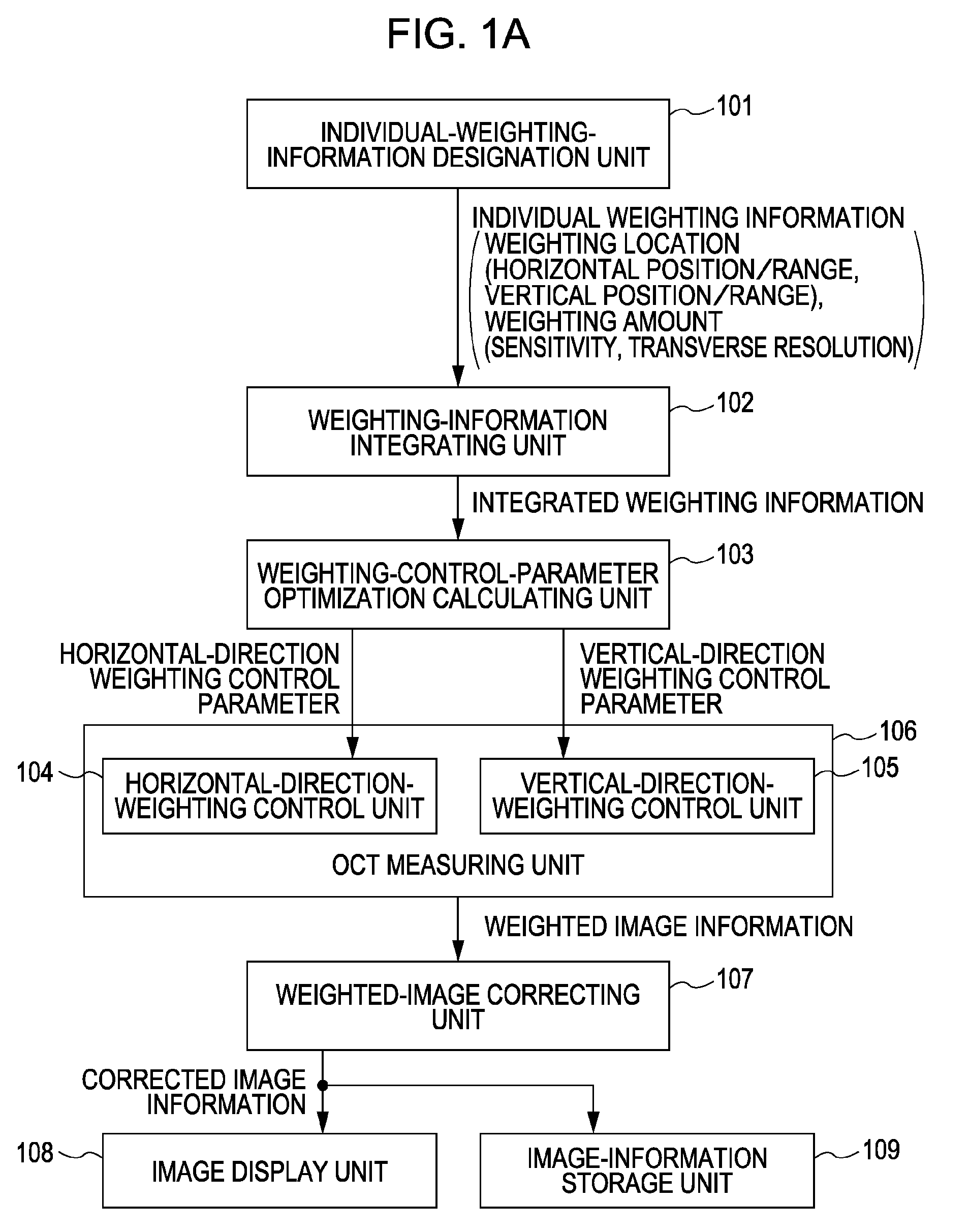
[0029]An image acquisition apparatus according to a first embodiment of the present invention for acquiring a tomographic image of an examination object by OCT is as follows.

[0030]The image acquisition apparatus includes a scanning unit disposed in a light path that guides signal light to be incident on the examination object towards the examination object. Specifically, the scanning unit is for scanning the signal light in the main scanning direction.

[0031]The image acquisition apparatus also includes a control unit configured to control the scanning unit such that the integration time of an optical interference signal per pixel in at least one predetermined area other than opposite ends, in the main scanning direction, of an image acquisition region scanned by a plurality of main scan lines is increased relative to that of areas other than the predetermined area.

[0032]The image acquisition apparatus that uses OCT (simply referred to as “OCT image acquisition apparatus” hereinafter...

second embodiment

[0109]An example including a dual-cycle resonant scanner according to a second embodiment of the present invention will now be described with reference to FIGS. 5D, 5E, and 5F.

[0110]In this embodiment, the resonance-type scanning optical systems of the main scanning direction in the first embodiment are changed to a single scanner device.

[0111]FIG. 5D schematically illustrates a dual-cycle resonance-type MEMS scanner device used in this embodiment that includes an outer-frame vibrator 904 and a reflective vibrator 905 integrally provided within the outer-frame vibrator 904. The outer-frame vibrator 904 and the reflective vibrator 905 are formed by an MEMS process using a single silicon wafer.

[0112]Referring to FIG. 6B, the outer-frame vibrator 904 vibrates at a basic resonance frequency of 2 kHz, whereas the reflective vibrator 905 vibrates at a resonance frequency of 6 kHz, which is three times that of the outer-frame vibrator 904. Thus, a section in the first embodiment where two ...

third embodiment

[0117]A third embodiment of the present invention will now be described.

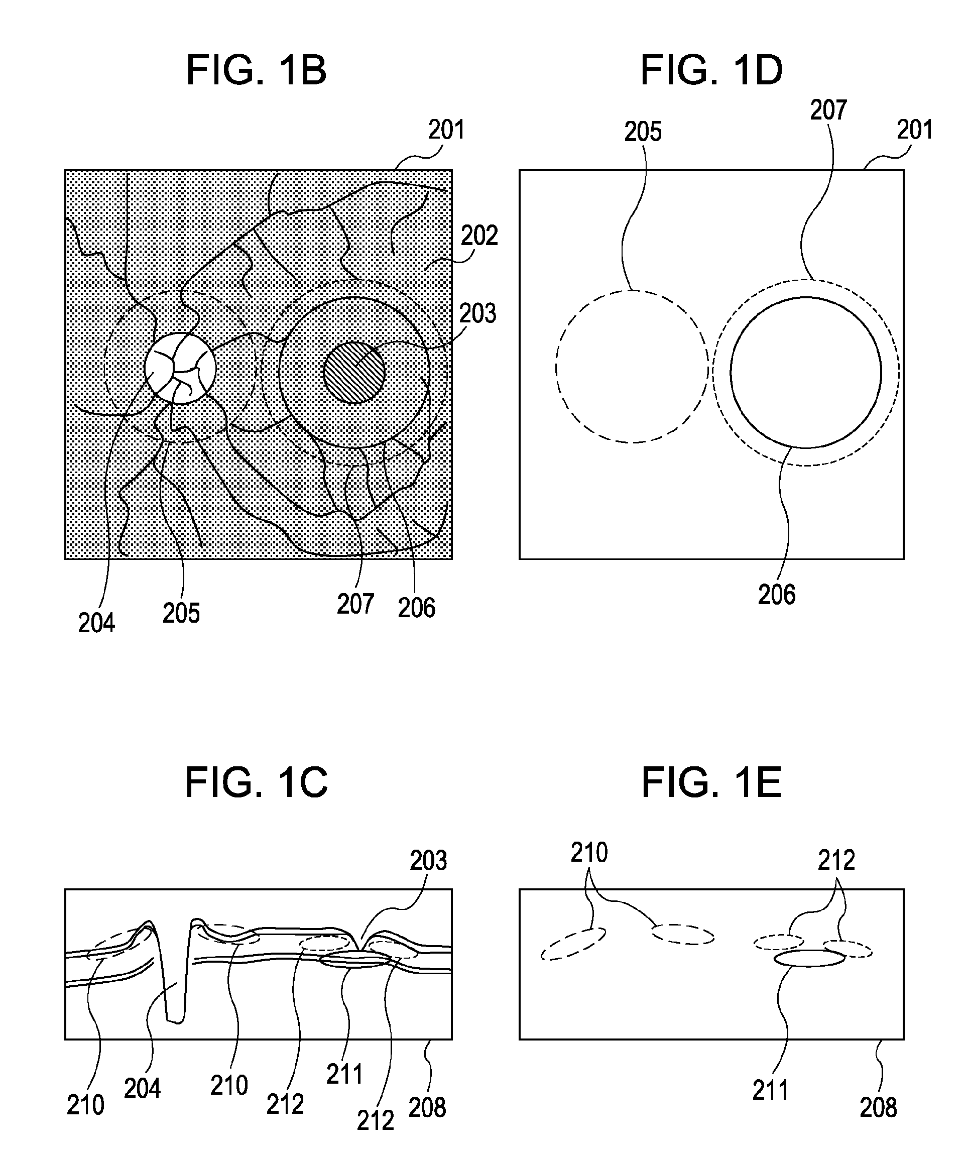
[0118]FIGS. 2C and 2D schematically illustrate how weighting control is performed on areas of importance in this embodiment. As shown in FIGS. 2C and 2D, the scan lines configured to scan the image acquisition region 201 in this embodiment are constituted by a first scan-line group 1301 and a second scan-line group 1302. Optical coherence tomographic images are acquired using these scan lines.

[0119]An OCT image acquisition apparatus using the first scan-line group 1301 and the second scan-line group 1302 will now be described.

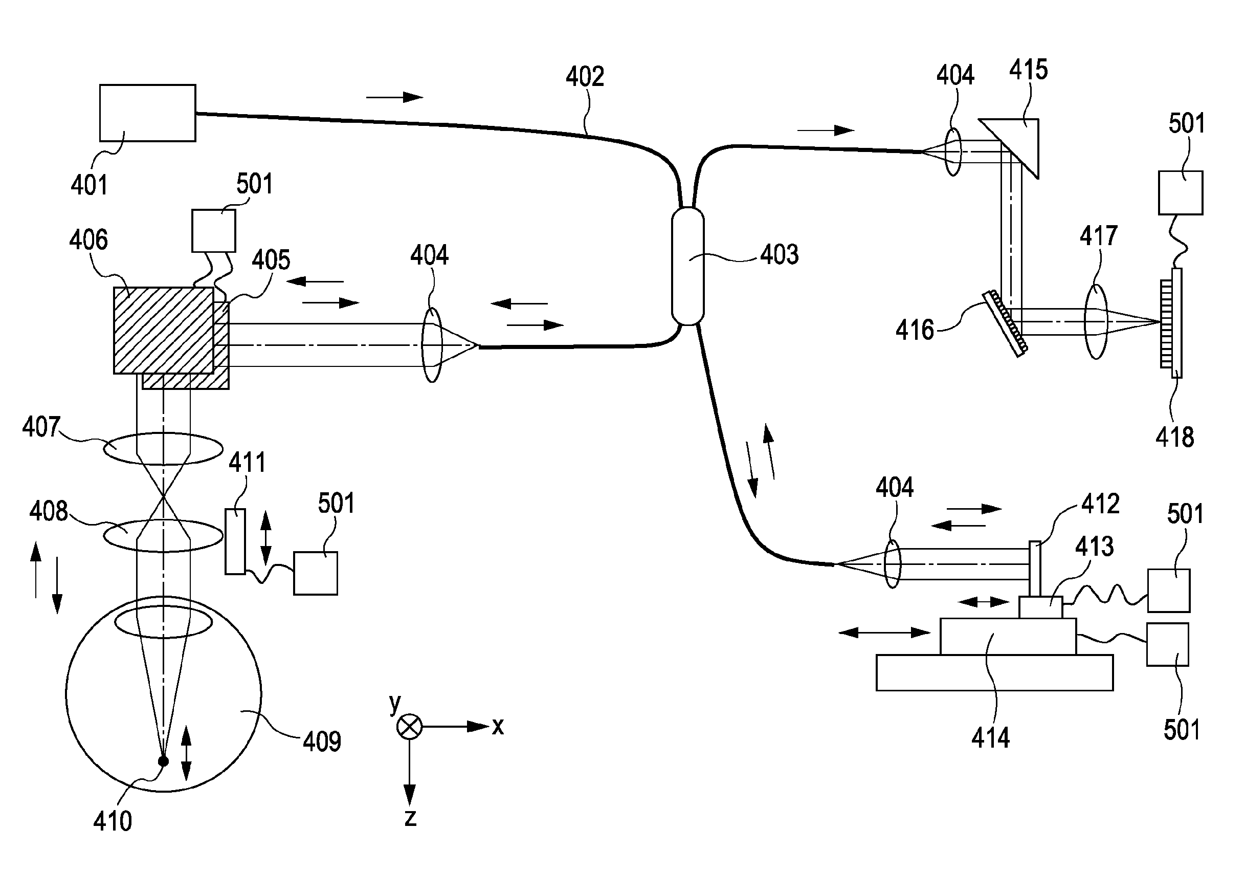
[0120]FIG. 3B schematically illustrates the configuration of an optical measuring system of an optical coherence measuring apparatus according to this embodiment. Light emitted from a light source 401 is sent to a fiber optical coupler 1401 via a single-mode optical fiber and is then equally transmitted to two optical fibers 402 by a distribution effect.

[0121]The two light beams are then di...


PUM


Abstract

An image acquisition apparatus that uses optical coherence tomography includes a scanning unit provided within a light path that guides signal light to be incident on an examination object towards the examination object and configured to scan the signal light in a main scanning direction; and a control unit configured to control the scanning unit such that an integration time of an optical interference signal per pixel in at least one predetermined area other than opposite ends, in the main scanning direction, of an image acquisition region scanned by a plurality of main scan lines is increased relative to that of an area other than the predetermined area.

Description

BACKGROUND OF THE INVENTION[0001]1. Field of the Invention[0002]The present invention relates to image acquisition apparatuses and image acquisition methods that use optical coherence tomography.[0003]2. Description of the Related Art[0004]In recent years, image acquisition apparatuses that use optical coherence tomography (referred to as “OCT” hereinafter) have been used in the opthalmologic field for acquiring fundus tomographic images.[0005]Accuracy in diagnosis is significantly affected by image distortion (motion artifact) caused by biological motion (eye motion in particular) occurring during a fundus image acquisition operation by OCT. A typical eye motion involves a three-dimensional involuntary eye movement of about 100 μm per second in the planar direction (referred to as “horizontal direction” hereinafter) as well as the depth direction (“referred to as “vertical direction” hereinafter) of a fundus.[0006]OCT mainly includes two methods, namely, time domain OCT (TD-OCT) an...

Claims


Application Information

Patent Timeline
Patent Type & Authority Patents(United States)
IPC IPC(8): A61B3/14
CPCA61B3/102A61B5/0066A61B5/0073A61B5/7242G01B9/02091G01B9/02048G01B9/02089A61B5/7257G01B2290/65G02B26/0833
Inventor SUGITA, MITSUROKOBAYASHI, SHUICHINOZATO, KOJIKATAYAMA, AKIHIROHIROSE, FUTOSHI
Owner CANON KK
Why Eureka
Try Eureka