Wideband dielectric waveguide filter

a dielectric filter and waveguide technology, applied in waveguides, resonators, electrical equipment, etc., can solve the problems of inability to achieve the desired step, inability to achieve the desired signal transmission, and inability to meet the needs of applications, etc., to achieve significantly miniaturized systems, reduce weight, and reduce the effect of cos

Active Publication Date: 2011-06-07
KNOWLES CAZENOVIA
View PDF7 Cites 10 Cited by
  • Summary
  • Abstract
  • Description
  • Claims
  • Application Information

AI Technical Summary

Benefits of technology

[0006]It is an object of the present invention to overcome the drawbacks associated with the prior art discussed above, in order to provide a waveguide filter having a wide pass-band without negatively affecting the resonator Q and also having an improved spurious response.
[0008]Resonators having this type of structure are called cavity or waveguide resonators. Cavity resonators exhibit not only one, but a number of harmonic resonances. Inevitably, filters built from these resonators exhibit undesired signal transmission at these harmonic resonances. For these types of resonators, the first harmonic resonance usually occurs at around 1.6 times the fundamental resonance, which may be unacceptable for some applications. The present inventors discovered that blind holes improve the coupling of the resonator also help to control the harmonics of the resonator. The first harmonic of the input / output resonators can be shifted to a higher frequency, that is, away from the fundamental resonance, to improve the spurious response of the filter.
[0009]According to one embodiment of the present invention, a wideband dielectric waveguide cavity filter is provided, including a dielectric body comprising a dielectric material and having two or more resonator sections. The dielectric body has a first surface and an opposed second surface defining a thickness dimension of the dielectric body therebetween, a pair of transversely opposed side surfaces extending in a longitudinal direction of the dielectric body and defining a length dimension of the dielectric body. A pair of longitudinally opposed end surfaces extend in a transverse direction of the dielectric body and define a width dimension of the dielectric body. The filter also includes two or more resonators that are longitudinally disposed along the longitudinal direction of the dielectric body so that adjacent ones of the two or more resonators are coupled to one another via a coupling mechanism. The dielectric body is substantially covered with a metal ground coating to define at least two uncoated regions surrounding a contact pad formed on one of the first surface and the opposed second surface of the dielectric body so that the contact pads are electrically isolated from the metal ground coating. One or more metallized blind holes are also provided, extending a distance from an opening on a metallized portion of the other one of the first surface and second surfaces of the dielectric body, e.g., the main or broad face surface of the dielectric body opposite the one which the contact pads are formed, toward a blind end thereof in the thickness direction of the dielectric body. The metallized blind holes, also interchangeably referred to herein as blind vias, effectively decrease a distance between a ground plane and the contact pads so as to effectively increase coupling between the resonators and external circuitry.
[0019]The wideband dielectric waveguide filters according to the present invention can be used in connection with microwave communications, radar or other applications wherein devices with frequency selective transmission characteristics are desired, specifically in the frequency range of 2 to 40 GHz. Both individual filters and multi-filter constructs such as duplexers can be realized using the present invention. Using high dielectric constant materials enables the miniaturization of wavelength dependent devices, which offers a size reduction in all three dimensions as well as a significantly lower weight compared to the more common air-filled cavity waveguide filters. The weight and volume reduction factors are typically on the order of 100:1 using dielectric materials with relative dielectric constants of approximately 23. In addition, the physical form of the invention allows the filters to be integrated into microwave systems by preferred means such as solder surface mount assembly technology. Frequently, the air filled cavity waveguide filters that would be replaced by the present invention ultimately control the size, weight and construction of the systems in which they are used. Along those lines, it is possible to realize both lower cost systems and significantly miniaturized systems.

Problems solved by technology

These steps are not desirable for the reasons explained above.
Inevitably, filters built from these resonators exhibit undesired signal transmission at these harmonic resonances.
For these types of resonators, the first harmonic resonance usually occurs at around 1.6 times the fundamental resonance, which may be unacceptable for some applications.

Method used


Image

  • Wideband dielectric waveguide filter
  • Wideband dielectric waveguide filter
  • Wideband dielectric waveguide filter

Examples


example

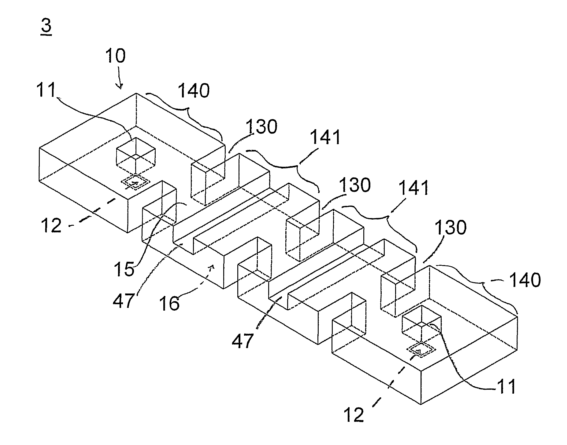
[0049]A 4 pole Chebyshev response band-pass waveguide cavity filter for operation at 10.5 GHz was fabricated using a proprietary Magnesium titanate, temperature stable ceramic with a relative dielectric constant of 23 to have the structure shown in FIG. 3. The overall dimensions of the part were 0.68×0.19×0.030 inches. The filter was fabricated from two layers polished ceramic layers, each 0.015 inch thick, in order to form blind cavities 11 with a depth of 0.015 inches. The blind cavities or blind vias 11 had dimensions of 0.02×0.02 inches and were formed directly above the contact pad islands 12, positioned on the longitudinal center-line of the filter at a distance of 0.045 inches from the end faces of the filter. Through holes forming post coupling irises 13′ were formed on the longitudinal center-line of the filter with dimensions of 0.036×0.053 inches and 0.036×0.058 inches with a via center-to-center spacing of 0.180 inches, defining the longitudinal dimension of the resonato...


PUM


Abstract

A waveguide-type dielectric filter suitable for wideband filter applications made of a metallized dielectric material is provided. The filter includes two or more mutually coupled resonators disposed in a longitudinal manner. The coupling between adjacent resonators is provided and adjusted by slots or through holes. The dielectric block is covered with metal ground coating with the exception of an uncoated area at the input and output that creates two contact pads on one surface of the dielectric block that are electrically isolated from the metal ground coating. Metallized blind holes are formed on the opposing surface of the dielectric block with respect to the contact pads. These blind holes effectively move the ground plane closer to the contact pad, which, in turn increases the coupling between the input and output resonators and external circuitry, which is essential for building wide bandwidth band pass filters.

Description

FIELD OF THE INVENTION[0001]The present invention relates to a waveguide-type dielectric filter suitable for narrow to wideband filter applications which is made from one or more blocks of dielectric material, such as a ceramic material.BACKGROUND OF THE INVENTION[0002]U.S. Pat. No. 6,566,986 discloses a dielectric filter composed of three or more rectangular parallel-piped dielectrics connected in line or integrally formed on a dielectric block. FIG. 7 illustrates one such waveguide-type dielectric filter. The filter comprises a metal coated rectangular parallel-pipe shaped dielectric block with input / output contact pads 112 made of a conducting film 71 as island-type contact pads surrounded by the insulating material of the dielectric block, and through holes 72 interposed between adjacent resonators 114 to form the resonators and coupling irises. As one skilled in the art would understand, the size and location of the contact pads 112, together with the size of the coupling irise...

Claims


Application Information

Patent Timeline
Patent Type & Authority Patents(United States)
IPC IPC(8): H01P1/208H01P7/06
CPCH01P1/2088H01P1/208
Inventor BATES, DAVID ALLENGOKTEN, MESUT
Owner KNOWLES CAZENOVIA
Why Eureka
Try Eureka