Method and electrode construction for electro-coagulation treatment of water and waste water

a technology of electrocoagulation treatment and electrode construction, which is applied in the direction of electrolysis components, instruments, chemistry apparatus and processes, etc., can solve the problems of affecting the operation of the system, affecting the current density of the cell, and not only costing a lot of chemicals, etc., to achieve the effect of maintaining the current density in the cell

Inactive Publication Date: 2011-06-14
10513547 CANADA INC
View PDF12 Cites 7 Cited by
  • Summary
  • Abstract
  • Description
  • Claims
  • Application Information

AI Technical Summary

Benefits of technology

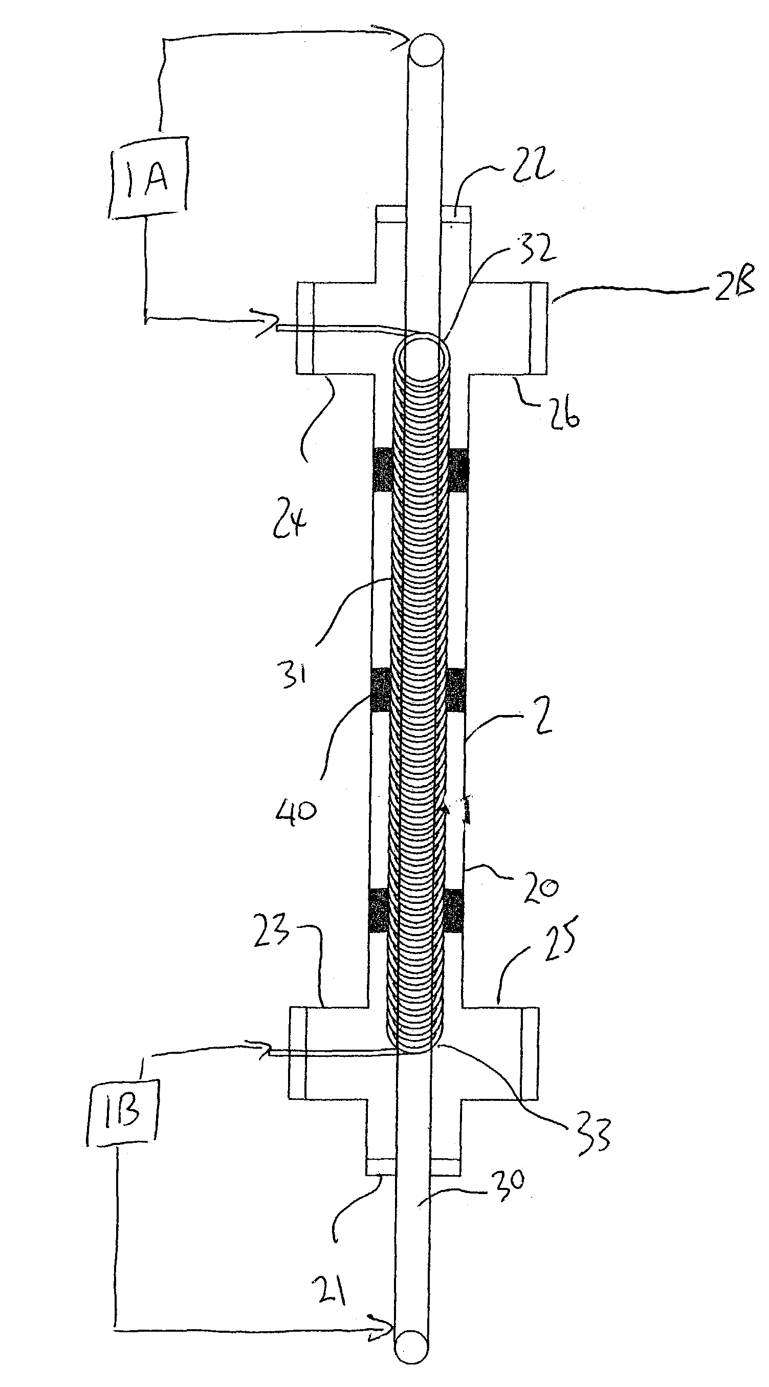
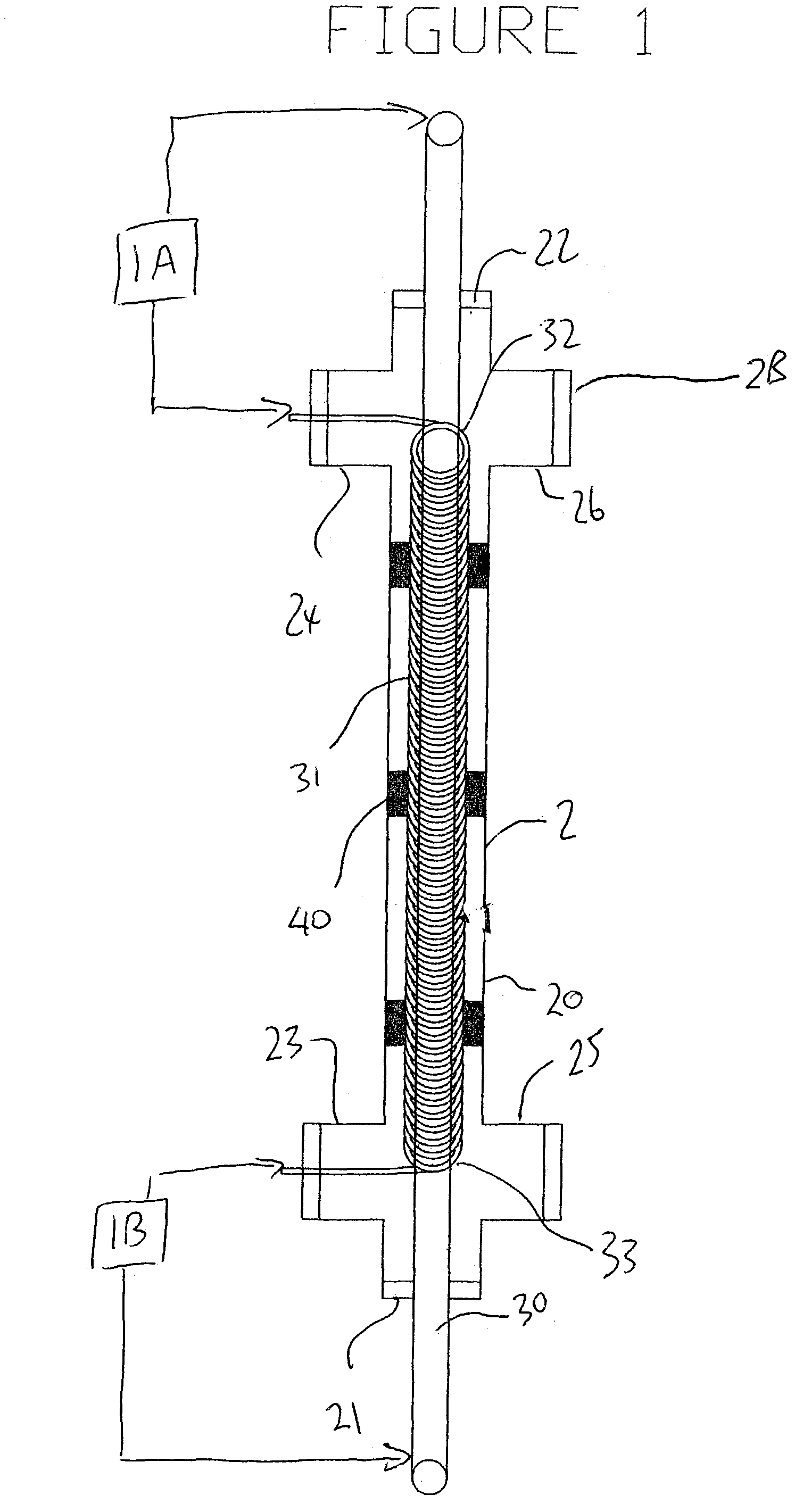
[0030]Preferably each end of the anode and each end of the elongate member forming the cathode is connected to a source of DC voltage so that the voltage along the length of the cell and thus the current density in the cell is maintained as constant as possible without significant drop off at one end of the cell.

Problems solved by technology

These chemicals are not only costly; they also contribute secondary pollution to the environment.
The cathode is subject to scale formation, which can impair the operation of the system.
Utilizing electro-coagulation treatment (ECT) systems to treat waste water was practised through most of the 20th century with limited success.
One significant problem which arises with continuous flow ECT systems is treating a sufficient rate of flow of water and waste water at reasonable cost, while at the same time preventing the system from clogging due to the formation of precipitates and corrosion scale deposited on the cathode.
Up till now there has been no suitable design of an electrolytic cell which provides an adequate treatment of the water and waste water to continuously remove the contaminants while at the same time preventing fowling of the cell.
Once fowling commences, this builds up until the cell becomes clogged.
There is at this time no effective way to self-clean the cell once the coagulation of particles has commenced.
While electro-coagulation is therefore known and accepted in principle, its commercial continuous flow application has been limited by this problem.

Method used


Image

  • Method and electrode construction for electro-coagulation treatment of water and waste water
  • Method and electrode construction for electro-coagulation treatment of water and waste water
  • Method and electrode construction for electro-coagulation treatment of water and waste water

Examples


experimental treatment trial 3

III. Experimental Treatment Trial 3

A. System Parameters[0087]1. The inlet flow rate was set at 9L / min.[0088]2. The total treatment time for trial 3 was 2:52 hours.

B. pH and Temperature Results[0089]1. The raw waste water temperature was 17.5 degrees C.[0090]2. The rapid mix chamber temperature was 19.5 degrees C.[0091]3. The slow mix chamber temperature was 19.5 degrees C.[0092]4. The settling tank temperature after 2 hours was 18 degrees C.[0093]5. The raw waste water pH was 7.6[0094]6. The waste water pH in the rapid mix chamber was 8.4[0095]7. The waste water pH in the slow mix chamber was 8.4[0096]8. The waste water pH in the settling tank was 8.3[0097]9. The waste water pH in the settling tank after 2 hours was 8.3[0098]10. The pH of the decant from the settling tank was?[0099]11.The conductivity of the raw waste water was 0.95 mS / cm[0100]12.The conductivity of the treated effluent was 0.90 mS / cm

C. Heavy Metal Analysis Results

[0101]

%JR #1RemovalParameter(raw)UnitsETS-3Efficienc...


PUM

PropertyMeasurementUnit
diameteraaaaaaaaaa
diameteraaaaaaaaaa
treatment timeaaaaaaaaaa

Abstract

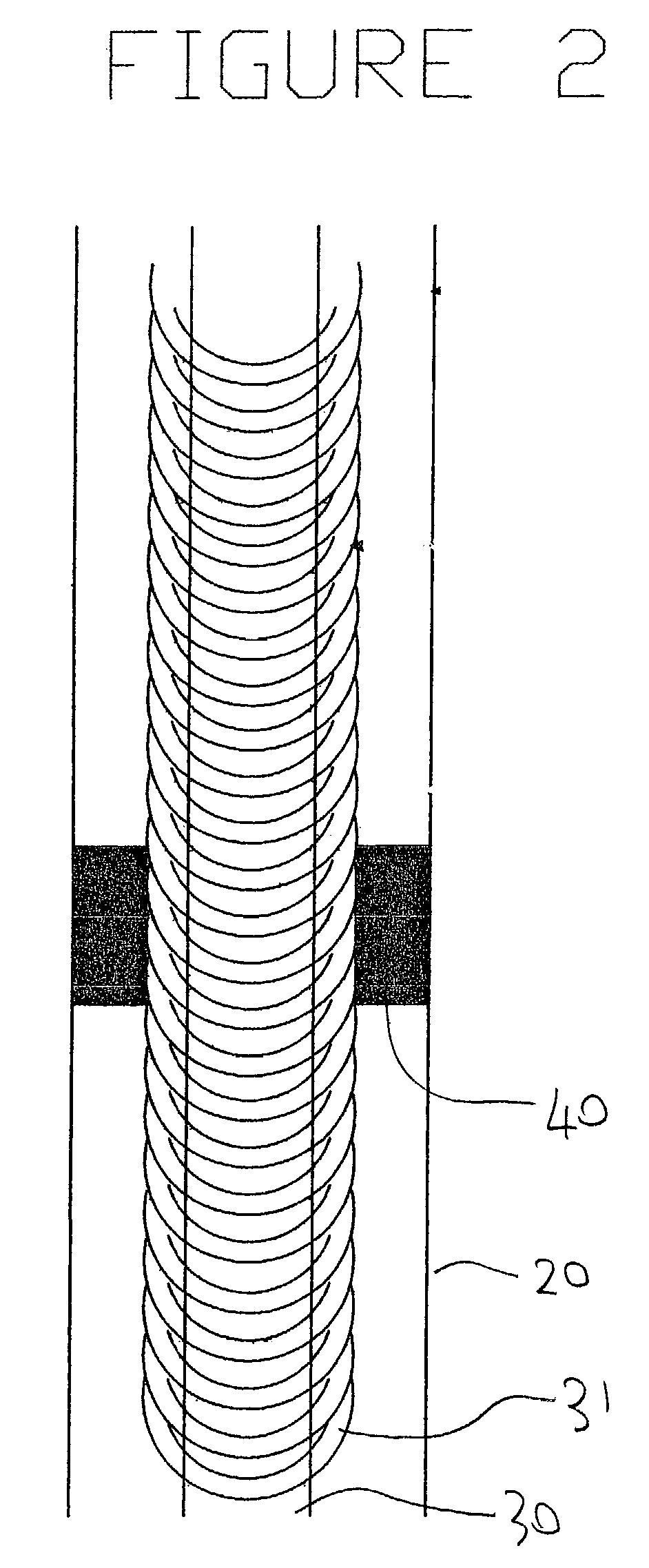
An improved method for the electro-coagulation c treatment of water and waste water includes an electrolytic cell having an anode and a helical cathode mounted longitudinally within a duct for receiving the contaminated water or waste water at one end and for discharging the treated water and electro-coagulated precipitates at the other end. The electro-coagulated precipitates can be subsequently separated by conventional flocculation, settlement and filtration systems. The anode forms a central longitudinal sacrificial rod defining a cylindrical outer surface and the helical cathode comprises an elongate wire coiled helically around and along the anode so as form a plurality of turns of the wire which turns are wrapped around the anode surface in the form of a constant helix of constant diameter with the turns spaced each from the next and spaced from the anode surface.

Description

[0001]This application claims priority under 35 U.S.C. 119 from Provisional Application Ser. No. 60 / 372,435, filed Apr. 16, 2002 and Provisional Application Ser. No. 60 / 420,332 filed Oct. 23, 2002.[0002]This invention relates to a method and electrode construction for the electro-coagulation treatment of water and waste water.BACKGROUND OF THE INVENTION[0003]Treatment of water and waste water by electro-coagulation is well known as a process by which contaminant particles can be coagulated to form precipitates which can be subsequently separated using conventional flocculation, settlement or filtration systems.[0004]Conventional coagulation is a chemical process in which the charged particles in colloidal suspension are neutralized by mutual collisions with counter ions. After the particle is neutralized, it will attract to other colloidal particles and agglomerate to form precipitates. It is generally accepted that coagulation occurs because of a reduction of the net surface charge...

Claims


Application Information

Patent Timeline
Patent Type & Authority Patents(United States)
IPC IPC(8): C02F1/463C02F1/461C02F1/52
CPCC02F1/46109C02F1/463C02F1/52C02F2201/4617C02F2001/46152C02F2101/20C02F2201/46145C02F2001/46133
Inventor WOYTOWICH, DAVID LORNEOGER, DANIEL ROBERTOGER, RONALD BRUCEDAVIE, CHRISTOPHER PAUL MARINO
Owner 10513547 CANADA INC
Why Eureka
Try Eureka