
Process and apparatus for the continuous production of a thin metal strip

a technology of thin metal strips and process equipment, which is applied in the direction of manufacturing tools, measuring devices, profile control devices, etc., can solve the problems of high production speed, width-dependent, uniform convective heat transfer or liquid metal temperature at the solidification front, and the inability to meet these requirements, so as to reduce the deviation of flatness

Active Publication Date: 2011-06-21
PRIMETALS TECH AUSTRIA GMBH
View PDF20 Cites 15 Cited by
  • Summary
  • Abstract
  • Description
  • Claims
  • Application Information

AI Technical Summary

Benefits of technology

[0027]Local temperature deviations in the hot strip which occur in longitudinally oriented zones can be specifically influenced if the temperature distribution in the metal strip is influenced in sections in a plane lying transversely with respect to the conveying direction of the metal strip as a function of the measured temperature profile. The more independently controllable cooling or heating zones are arranged transversely with respect to the strip running direction, the better the temperature profile can be controlled at the cast metal strip.
[0047]Another possible way of minimizing flatness deviations on the hot strip consists in the fact that a strip thickness profile measuring device for determining the strip thickness profile is arranged in a plane lying transversely with respect to the conveying direction of the metal strip, and this strip thickness measuring device is assigned an evaluation device for recording and converting the measured values.

Problems solved by technology

Experience gained in the production of hot-rolled steel strip has shown that it is very difficult to satisfy these requirements when using the two-roll casting process on a corresponding casting installation.
One major cause of difficulties in achieving standard flatness values results from the high production speed with the production process selected for the cast intermediate product.
The metal strip is produced in a process with extremely high solidification rates directly in a format with extreme width / thickness ratios, which although eliminating a large number of roll passes with a view to achieving the desired hot strip final thickness, means that width-independent, uniform convective heat transfer or liquid metal temperature at the solidification front (when forming the strand shells) are only possible to a limited extent, on account of the highly turbulent flow conditions in the metal bath.
This results in a temperature / width profile on the cast metal strip when it emerges from the casting nip between the casting rolls which is subject to fluctuations of up to 100% and above, based on the supercooling with respect to the equilibrium solidus temperature, so that internal stress conditions and creep properties which cause unevenness in the cast strip are present.
The in-line rolling of a cast metal strip can also contribute to the formation of further unevenness if the strip inlet temperature (temperature at which the metal strip enters the rolling stand) is relatively uneven over the width of the metal strip or the inlet strip profile is unknown or fluctuates.
At the low starting thicknesses preferred, it is not possible to influence the relative strip profile without any flatness defects.
Furthermore, the high roughness of the metal strip, caused by the casting operation and by any scaling, leads to a high level of wear to the working rolls.
These wear phenomena on the working rolls occur to an increased extent in the region of the strip edges and lead to defects in the strip profile.

Method used


Image

  • Process and apparatus for the continuous production of a thin metal strip
  • Process and apparatus for the continuous production of a thin metal strip
  • Process and apparatus for the continuous production of a thin metal strip

Examples


Embodiment Construction

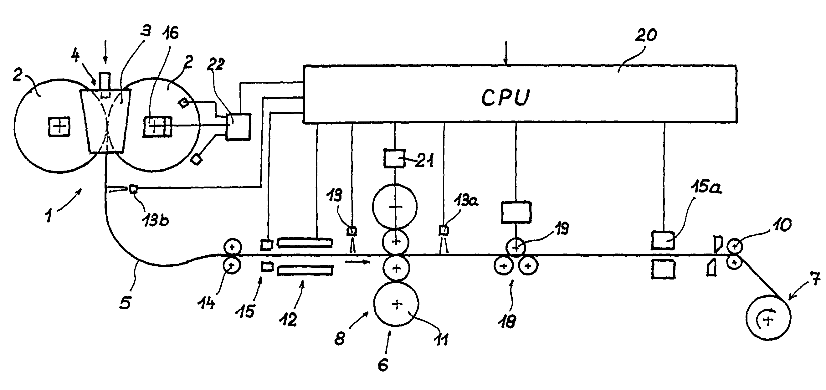
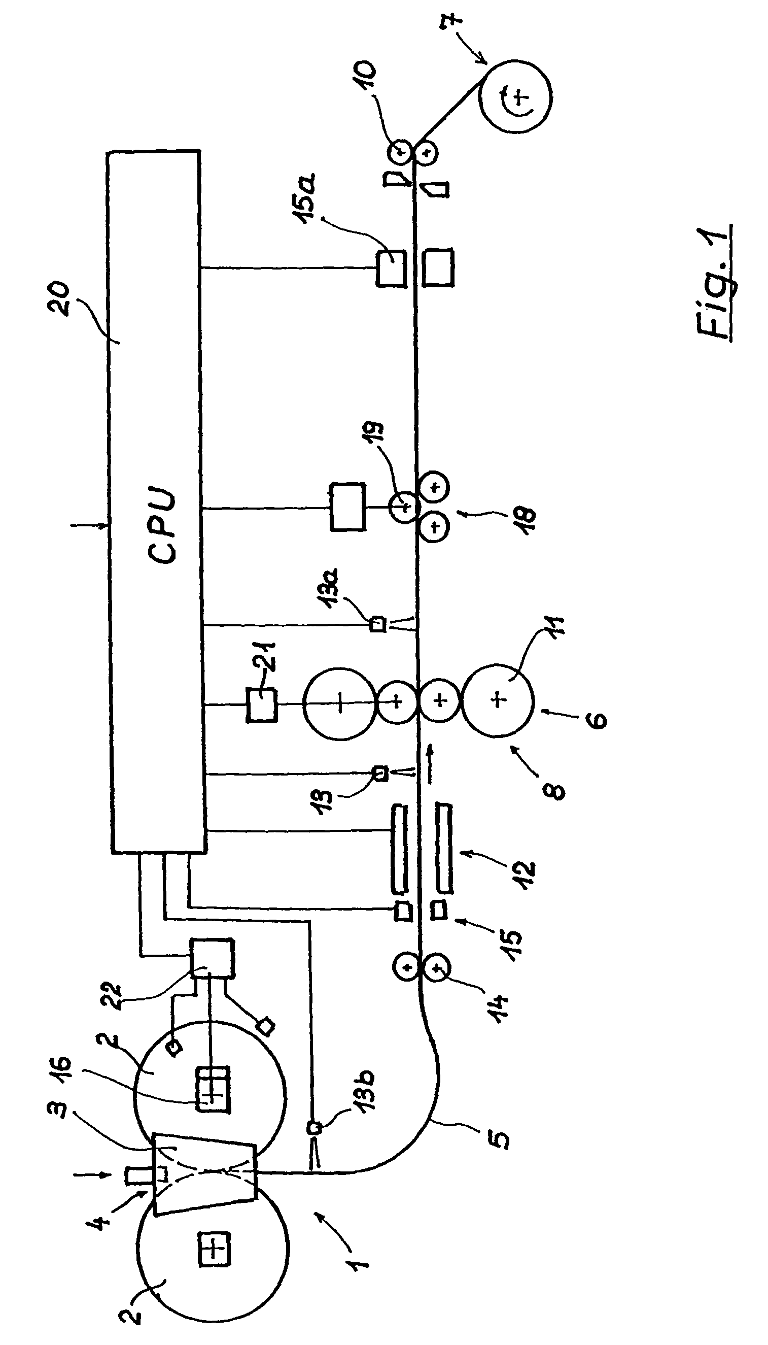
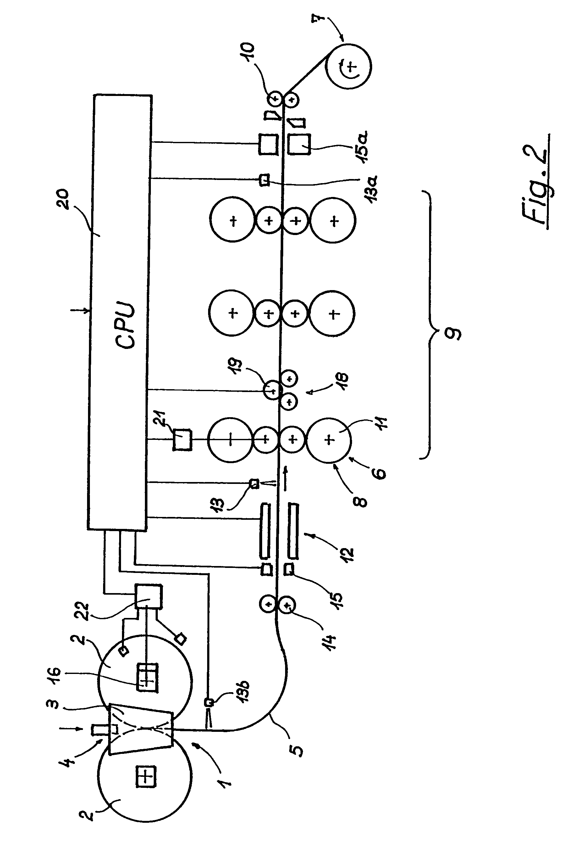
[0066]FIGS. 1 and 2 illustrate two embodiments of an installation for producing a steel hot strip in the form of a diagrammatic longitudinal section comprising the main components of the installation, as well as measurement and control devices for the production of a thin hot strip within the flatness tolerances which are customary for thin hot strip. The basic structure of the installation is the same when producing a nonferrous metal strip.

[0067]In a two-roll casting device 1, steel melt is introduced into a melt space 4, which is formed by two internally cooled, oppositely rotating casting rolls 2 and two side plates 3 positioned at the end sides of the casting rolls, and a cast steel strip 5 with a predetermined cross-sectional format is discharged vertically downwards from a casting gap formed by the casting rolls 2 and the side plates 3. After the steel strip has been diverted into a horizontal conveying direction, the cast steel strip is subjected to a reduction in thickness ...


PUM

PropertyMeasurementUnit
Lengthaaaaaaaaaa
Thicknessaaaaaaaaaa
Thicknessaaaaaaaaaa

Abstract

Processes for continuous production of a thin metal strip, in particular a steel hot strip, directly from a metal melt and with a strip cast thickness of <10 mm by the roll-casting process. The cast metal strip is fed for in-line thickness reduction, and then to a storage device. To achieve a high-quality, hot-rolled metal strip with flatness tolerances comparable to those which can currently be achieved in the production of hot-rolled metal strip from continuous-cast thin slabs or slabs, at cast thicknesses of between 40 and 300 mm, in a continuous production process starting directly from metal melt. With the low strip cast thickness, a flatness measurement is performed on the moving metal strip, and the measurement results of this flatness measurement are used to influence the flatness of the metal strip in a targeted way.

Description

CROSS REFERENCE TO RELATED APPLICATIONS[0001]The present application is a 35 U.S.C. §§371 national phase conversion of PCT / EP2005 / 010129 filed 20 Sep. 2005, which claims priority of Austrian Application No. A 1708 / 2004 filed 13 Oct. 2004. The PCT International Application was published in the German language.BACKGROUND OF THE INVENTION[0002]The invention relates to a process and an apparatus for the continuous production of a thin metal strip, in particular a steel hot strip, directly from a metal melt and with a strip cast thickness of <10 mm after a roll-casting process using a roll-casting device.[0003]In particular, the invention relates to a process and an apparatus for producing a hot-rolled steel strip with a strip cast thickness of <6 mm. The hot strip thickness when the hot strip is stored following the rolling deformation is between 0.3 and 4 mm.[0004]The proposed roll-casting processes on which the invention is based encompass all types of casting processes in which...

Claims


Application Information

Patent Timeline
IPC IPC(8): B21B37/28
CPCB21B1/463B21B37/28B22D11/0622B21B37/44B21B38/02Y10T29/49991B21B2263/02B21B2263/04B21B2261/21B22D11/06B21B1/46
Inventor FLICK, ANDREASSCHWEIGHOFER, ANDREASBRUMMAYER, MARKUSHOHENBICHLER, GERALDECKERSTORFER, GERALD
Owner PRIMETALS TECH AUSTRIA GMBH
Learn More