
Scanning X-ray inspection system using scintillation detection with simultaneous counting and integrating modes

a technology of x-ray inspection and simultaneous counting, applied in the field of x-ray screening systems, can solve the problems of poor resolution, high noise content, and less effective items for such items, and achieve the effects of reducing pixel-to-pixel cross-talk, fast and efficient, and enhancing discrimination of different materials

Inactive Publication Date: 2011-06-21
CONTROL SCREENING
View PDF5 Cites 27 Cited by
  • Summary
  • Abstract
  • Description
  • Claims
  • Application Information

AI Technical Summary

Benefits of technology

This approach results in improved image quality with higher resolution and reduced noise, enabling effective detection of contraband such as bombs, firearms, and narcotics by accurately distinguishing between different materials and their overlays.

Problems solved by technology

Although transmission systems can be used to detect items with lower Z, in practice they are often considered to be less effective for such items.
Among the more troublesome problems with systems that use both X-ray transmission and Compton scatter to create images are poor resolution and high noise content.
Some of the causes of these problems can be traced to: a) the relatively poor light collection methods used in converting X-ray photons to light photons; and b) photon integration.
Detectors using relatively slow phosphors oftentimes create undesirably blurred images owing to the slow response time of the excited phosphor.
Although photon integration used in conventional signal generation and processing affords advantages at high X-ray rates, it can result in noisy images, particularly in cases where the transmitted or scattered X-ray rates are relatively small.
The Fujii et al. apparatus employs long persistence phosphor type X-ray detectors and photon integration, resulting in relatively low resolution.
A further difficulty arises from the wide dynamic range of X-ray intensity that practical scanning systems must accommodate.
The impact of this wide range is especially challenging as a scanned object comprising portions with very different radiological character (i.e., photoelectric absorption and Compton scattering behavior) passes through the inspection zone.

Method used


Image

  • Scanning X-ray inspection system using scintillation detection with simultaneous counting and integrating modes
  • Scanning X-ray inspection system using scintillation detection with simultaneous counting and integrating modes
  • Scanning X-ray inspection system using scintillation detection with simultaneous counting and integrating modes

Examples


Embodiment Construction

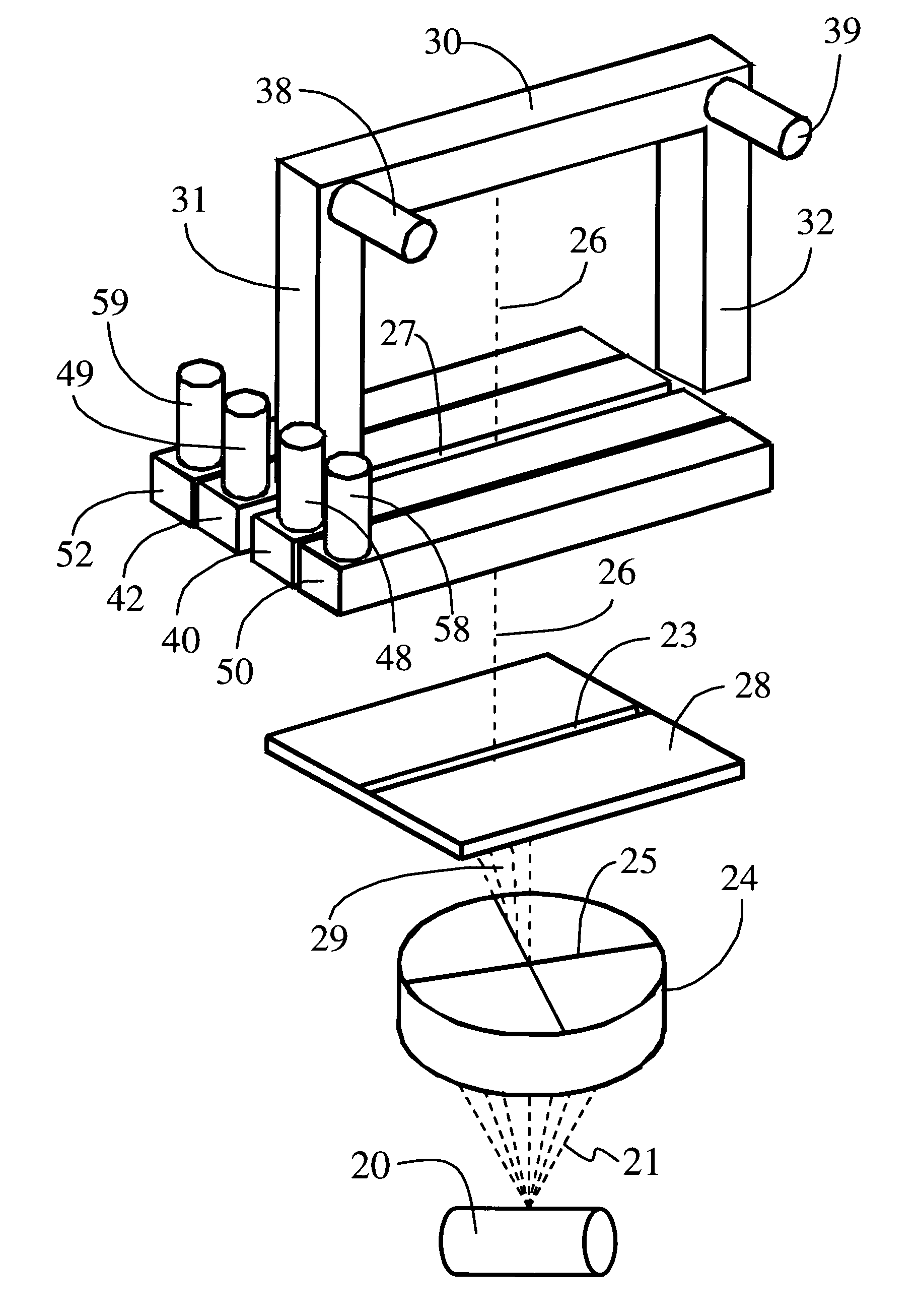
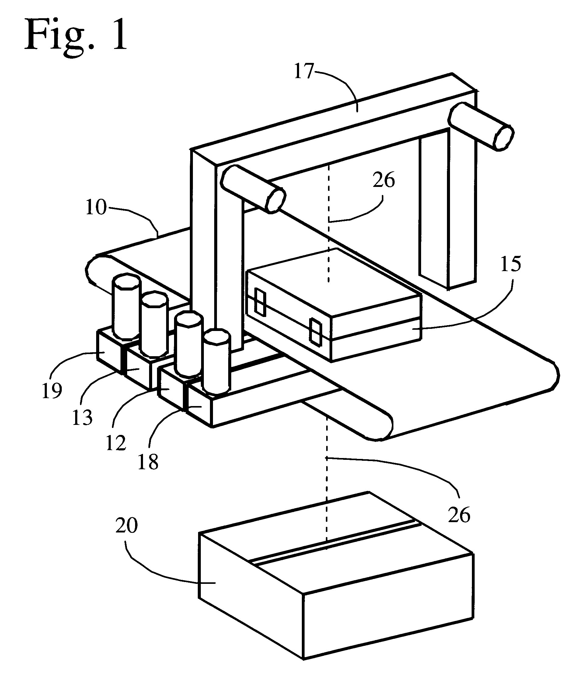
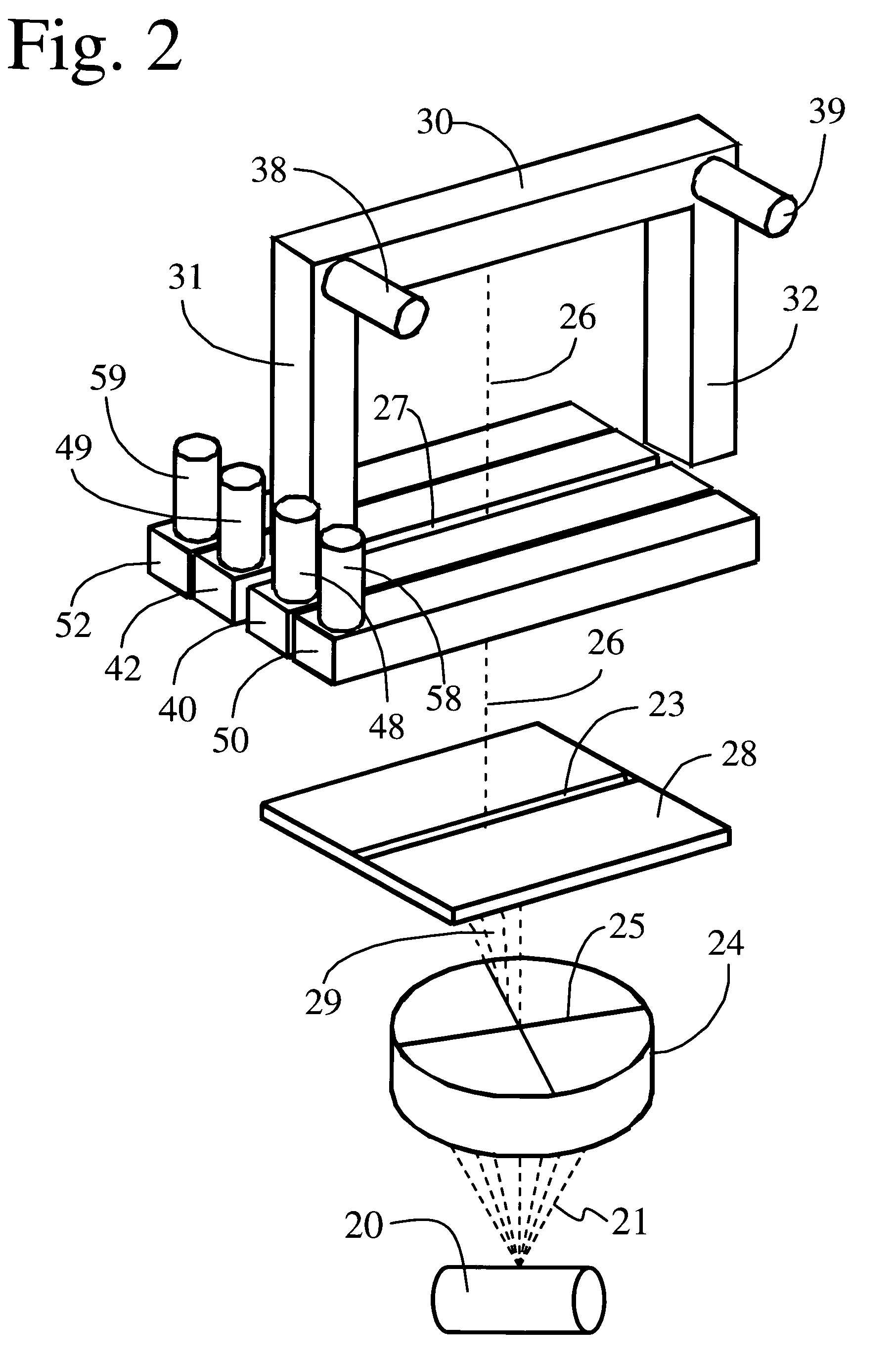
view of a scintillator detector system usable in the present system; FIG. 11B is a view of the detector system of FIG. 11A in side elevation;

[0037]FIG. 12A is a graphical plot of the output of a detector system processed in photon counting or integrating modes; FIG. 12B is a graphical plot in which the photon counting data of FIG. 12A are rescaled;

[0038]FIG. 13 is a graphical plot of multiplier factors used in connection with soft-switching incorporated in some embodiments of the invention;

[0039]FIG. 14 is a graphical plot of the data of FIG. 12A showing the effects of scaling and the multiplier factors of FIG. 13;

[0040]FIG. 15 depicts in side plan view a prototypical step wedge used in calibration of the present system;

[0041]FIG. 16 depicts a flow diagram of data processing providing edge enhancement in an operating mode of the present system;

[0042]FIG. 17 is a portion of computer code used to provide edge filtering in some embodiments;

[0043]FIG. 18 depicts a flow diagram of data p...


PUM

PropertyMeasurementUnit
θaaaaaaaaaa
θaaaaaaaaaa
sizesaaaaaaaaaa

Abstract

X-ray radiation is transmitted through and scattered from an object under inspection to detect weapons, narcotics, explosives or other contraband. Relatively fast scintillators are employed for faster X-ray detection efficiency and significantly improved image resolution. Scatter and transmission images of the object are displayed, at least one being colorized in accordance with the effective atomic number of constituents of the object. Soft switching between photon-counting and photon integration modes reduces noise and significantly increases overall image quality.

Description

RELATED U.S. APPLICATION DATA[0001]This application claims the benefit of U.S. Provisional Application Ser. No. 61 / 188,575, filed Aug. 11, 2008, and entitled “Scanning X-Ray Inspection System Using Scintillation Detection With Simultaneous Counting And Integrating Mode,” and U.S. Provisional Application Ser. No. 61 / 192,115, filed Sep. 15, 2008, and entitled “Scanning X-Ray Inspection System Using Scintillation Detection With Simultaneous Counting And Integrating Mode,” which are both incorporated herein in the entirety by reference thereto.BACKGROUND OF THE INVENTION[0002]1. Field of the Invention[0003]The present invention relates to X-ray screening systems for airport luggage, cargo, parcels, inter-modal containers, and the like; and, more particularly to screening systems that utilize radiation transmitted through and scattered from an object under inspection to detect weapons, narcotics, explosives or other contraband.[0004]2. Description of the Prior Art[0005]X-ray inspection s...

Claims


Application Information

Patent Timeline
Patent Type & Authority Patents(United States)
IPC IPC(8): G01N23/201
CPCG01V5/0025G01V5/0016G01V5/222G01V5/22
Inventor KRAVIS, SCOTT D.GEISEL, KARL E.VOIGTLAND, KARLMARIO, ARTHUR W.
Owner CONTROL SCREENING
Learn More